Eureka AIR delivers breakthrough ideas for toughest innovation challenges, trusted by R&D personnel around the world.

Asymmetric Composite Acoustic Wave Sensor

a composite acoustic wave and sensor technology, applied in piezoelectric/electrostrictive/magnetostrictive devices, piezoelectric/electrostriction/magnetostriction machines, electrical transducers, etc., can solve problems such as noise signals and reading errors, corrosion or even explosive hazards, etc., to improve the responsiveness to physical measurements, improve coupling for operation, and high dynamic range

Inactive Publication Date: 2010-03-04
MICROSEMI CORP HIGH PERFORMANCE TIMING
View PDF15 Cites 17 Cited by
  • Summary
  • Abstract
  • Description
  • Claims
  • Application Information

AI Technical Summary

Benefits of technology

[0014]It is therefore an object of the present invention to provide a thick piezoelectric composite acoustic wave device having improved coupling for operation in overtone mode, while still providing improved responsiveness to a physical measurand with high dynamic range.
[0016]It is yet another object of the present invention to provide a sensor which may operate efficiently in hostile environments such as high pressure, and reactive ambient conditions.
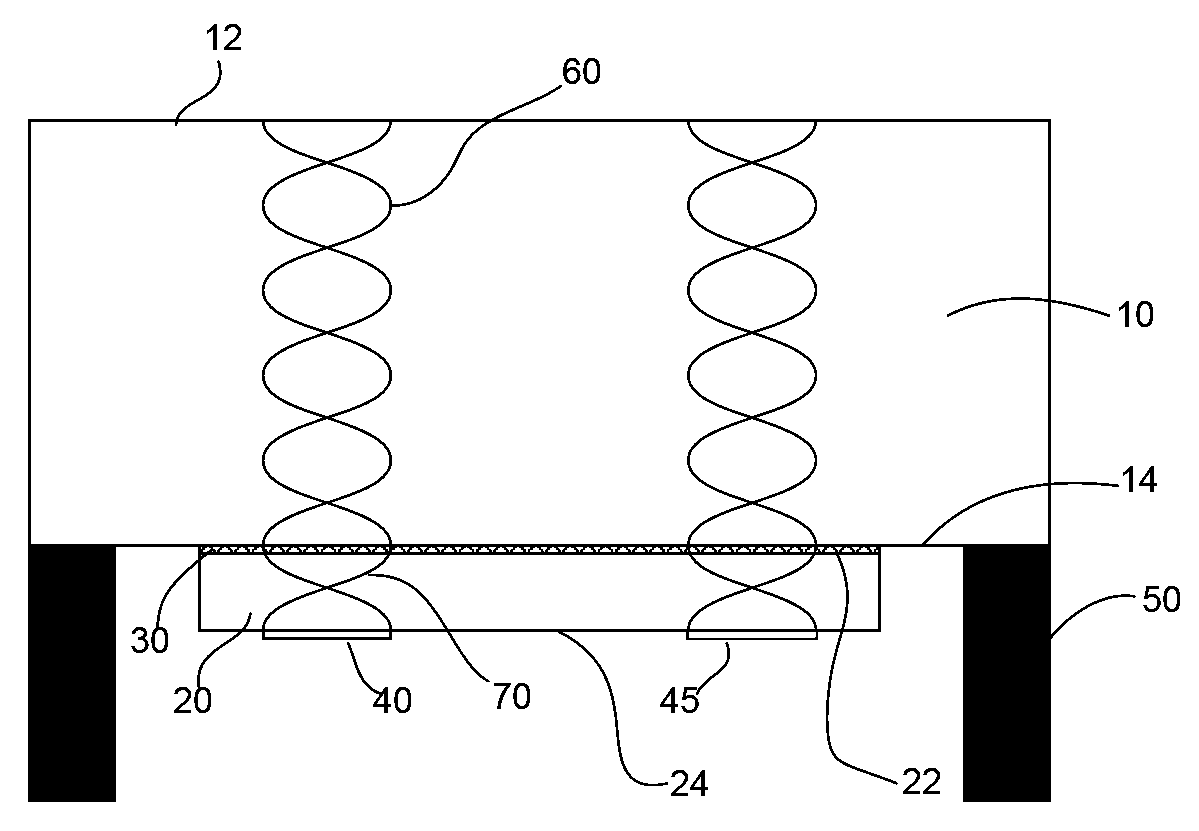
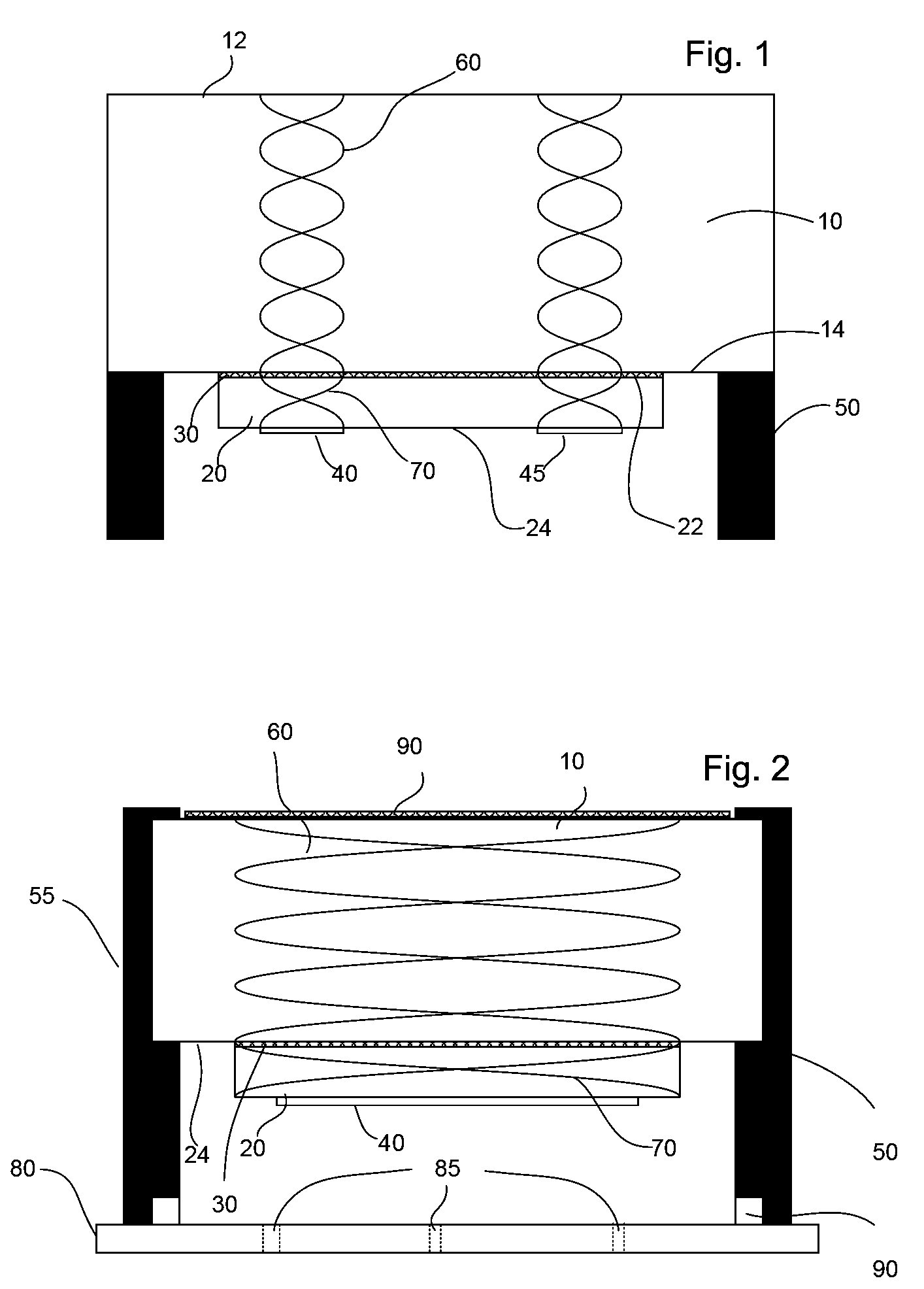
[0018]To that end, in its simplest form, the invention provides a composite structure comprising a rigid structural element (a protector plate hereinafter), coupled to a piezoelectric plate, so as to provide continuous mechanical displacement amplitude, phase and stress relationship at the energy interface formed therebetween. By selecting specific materials and dimensioning those materials in accordance with the principles disclosed herein, a resonant frequency wave imparted to one side of the composite structure, shall travel to the other side and back with minimal energy loss, without presenting undue mechanical stresses to any joining interfaces, and with good acoustic coupling of the wave properties to the conditions on the other side. Doing so will allow the composite to present the electrical efficiency of fundamental-mode oscillatory operation, without suffering from the disadvantages of a thick piezoelectric plate while exhibiting the mechanical toughness of a thick plate. To that end there is provided a composite acoustic wave device having a target resonant frequency, associated with a selected polarization of acoustic displacement. The device comprises a rigid protector plate mounted to a mechanical mount, the protector plate comprising a material having high quality acoustical characteristics. The protector plate has a driven face and a sensing face, and further has a thickness which is substantially a multiple of half wavelength of said resonant frequency. A piezoelectric plate having a thickness of substantially a multiple of half wavelength of the resonant frequency in the plate is further provided. The piezoelectric plate has an excitation face having at least one transducer electrode deposited thereupon, which together with at least one other electrode form a transducer interconverting electrical and acoustical energy within the piezoelectric plate. The piezoelectric plate is supported from the protector plate. An energy interface is formed between the driven face and a driving face of said piezoelectric plate, such that a wave of said resonant frequency traveling between the excitation face and the sensing face, shall form a substantially continuous-phase wave, at substantially peak displacement amplitude, at the energy interface.

Problems solved by technology

However the sensitive electronics are then subjected to, in the least, noise signals and reading errors and, in the extreme, to corrosion or even explosive hazards.
However passivation is not complete and electrical components of the circuit are still exposed to capacitive loading and noise injection.
Moreover, most passivation methods require the use of material having poor acoustic characteristics compared to single crystal materials.
Finally, these passivated surface wave based sensors exhibit undesirably high shear rate for many liquid phase measurements.
While such sensors potentially address many sensor applications, they are not ideal, for instance, in measuring fluids in oil production, especially in down-well environments.
Therefore, the finite strength of the material limits the operating pressure to which the sensor may be exposed.
Even if the material is sufficiently strong to withstand the pressure, the nonlinear effect on the sensor of membrane flexure will severely affect the sensor characteristics.
This however suffers from reduced acoustic coupling, reduced efficiency and dynamic range, and other disadvantages, whether the piezoelectric material is operated at fundamental or at overtone operating mode.
Yet another disadvantage of the present piezoelectric sensors is lack of resistance to harsh chemicals, abrasion, and the like.
In such devices, the lateral extent of the added layer is limited by the piezoelectric plate size, and does not support the piezoelectric, but is rather supported therefrom.
Thus film deposition methods do not provide additional resistance to pressure or encapsulation from environmental damage.
An intentional acoustic mismatch between the sapphire and the piezoelectric plate allows the device to have a very high reflection of the energy trapped therein, and thus generate a number of extremely sharp transfer peaks.
However, the weak acoustic coupling and the compressional wave operation mode make the device ill suited for liquid-phase sensor duty, which requires a shear wave.

Method used


Image

  • Asymmetric Composite Acoustic Wave Sensor
  • Asymmetric Composite Acoustic Wave Sensor
  • Asymmetric Composite Acoustic Wave Sensor

Examples


Embodiment Construction

[0035]The following is a description of exemplary preferred embodiments and several modifications thereof. The description provided comes by way of illustrative example only, and the skilled in the art will recognize that many other variations are viable and equivalent to the disclose examples and embodiments. The invention extends to all such equivalents and obvious modifications.

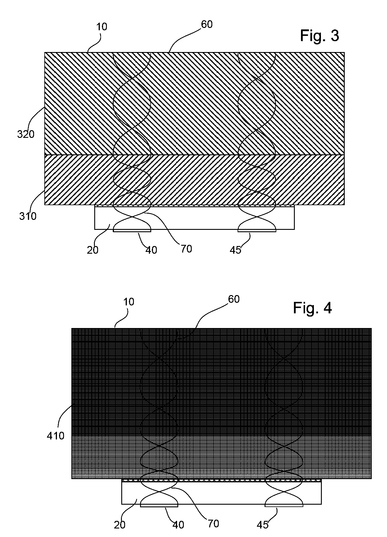
[0036]FIG. 1 depicts a cutout of an acoustic device in accordance with the preferred embodiment of the invention. Protector plate 10 is coupled to a piezoelectric plate 20 so as to provide substantially continuous phase relationship at the interface therebetween. The protector plate has a driven face 14, and an opposing loaded face 12. When operational, the loaded face will be immersed in the environment to be sensed. The driven face 14 interfaces with a driving face 22 of the piezoelectric plate, and receives acoustic energy therefrom. The ideal boundary conditions between two rigidly bonded materials req...


PUM


Abstract

A composite acoustic wave device provides improved protection from environmental factors while maintaining high electrical characteristics and dynamic range is provided. The device comprises a rigid protector plate having high quality acoustical characteristics and a thickness which is a multiple of half wavelength of the resonant frequency. A piezoelectric plate is coupled to the protector plate, is supported therefrom, and forms an energy interface therewith. The piezoelectric and protector plates are dimensioned such that a wave of resonant frequency traveling between the excitation face and the loaded / sensing face, forms a substantially continuous-phase wave, at substantially peak amplitude, at the energy interface. By doing so the device decouples the electrical thickness of the wave device from the mechanical thickness thereof.

Description

FIELD OF THE INVENTION[0001]The present invention relates generally to acoustic wave sensors, and more particularly to a hybrid acoustic wave sensors for operation at harsh and or high baric difference environments.BACKGROUND OF THE INVENTION[0002]Piezoelectric sensors are well known. They are used for sensing material properties such as viscosity and density, for detecting the presence of certain materials in an environment, for measuring purity of fluid substance, and the like. Structures known for acoustic sensing range from the simple crystal resonator, crystal filters, acoustic plate mode devices, Lamb wave devices, and the like. Briefly, these devices comprise a substrate of piezoelectric material such as quartz, langasite or lithium niobate, or thin films of piezoelectric material, such as aluminum nitride, zinc oxide, or cadmium sulfide, on a non-piezoelectric substrate. The substrate has at least one active piezoelectric surface area, which in most cases is highly polished....

Claims


Application Information

Patent Timeline
IPC IPC(8): H01L41/083
CPCH04R17/00
Inventor ANDLE, JEFFREY C.HASKELL, REICHL B.
Owner MICROSEMI CORP HIGH PERFORMANCE TIMING
Why Eureka
Eureka Blog
Learn More