
Generation of depth map for an image

a depth map and image technology, applied in image analysis, image enhancement, instruments, etc., can solve the problems of difficult 2d to 3d conversion task, low resolution, complex digitalization of images, etc., and achieve the effect of improving the depth map of images

Inactive Publication Date: 2010-02-25
KONINKLIJKE PHILIPS ELECTRONICS NV
View PDF12 Cites 94 Cited by
  • Summary
  • Abstract
  • Description
  • Claims
  • Application Information

AI Technical Summary

Benefits of technology

The invention provides an improved method for generating an image depth map, which can better correspond to the depth characteristics of an image and improve the depth data for background areas. The method involves generating a depth indication map by filtering the image based on image characteristics and image objectives, and then generating an image depth map by modifying the depth indication map based on the image characteristics of the image and the depth profile of the image. The invention can be implemented with low computational resource requirements and can be used for a variety of images. The technical effects of the invention include improved correspondence between depth transitions and borders of image objects, easier generation of an image depth map, and improved depth information for background areas.

Problems solved by technology

Furthermore, the digitalization of images allows complex manipulations and processing which provides opportunities not previously available.
However, the applications face the basic obstacle that the 2D to 3D conversion task is fundamentally very difficult.
Accordingly, most known approaches are heuristic and very few methods attempt the recovery of absolute depth or of the exact ordering of the depths of the various objects forming a scene.
However, these approaches tend to work only within restrictive conditions and result in poor quality depth maps that are not suitable for e.g. visualization tasks.
However, these approaches tend to require large training sets of image / depth map pairs, which tend to be available for very specific scenes only.

Method used


Image

  • Generation of depth map for an image
  • Generation of depth map for an image
  • Generation of depth map for an image

Examples


Embodiment Construction

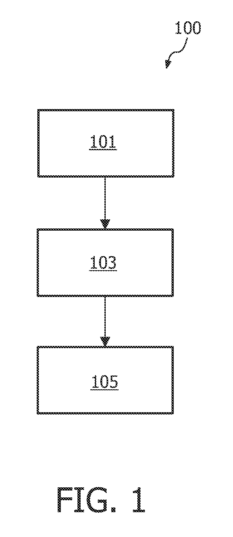
[0053]FIG. 1 illustrates an example of an image processing unit in accordance with some embodiments of the invention.

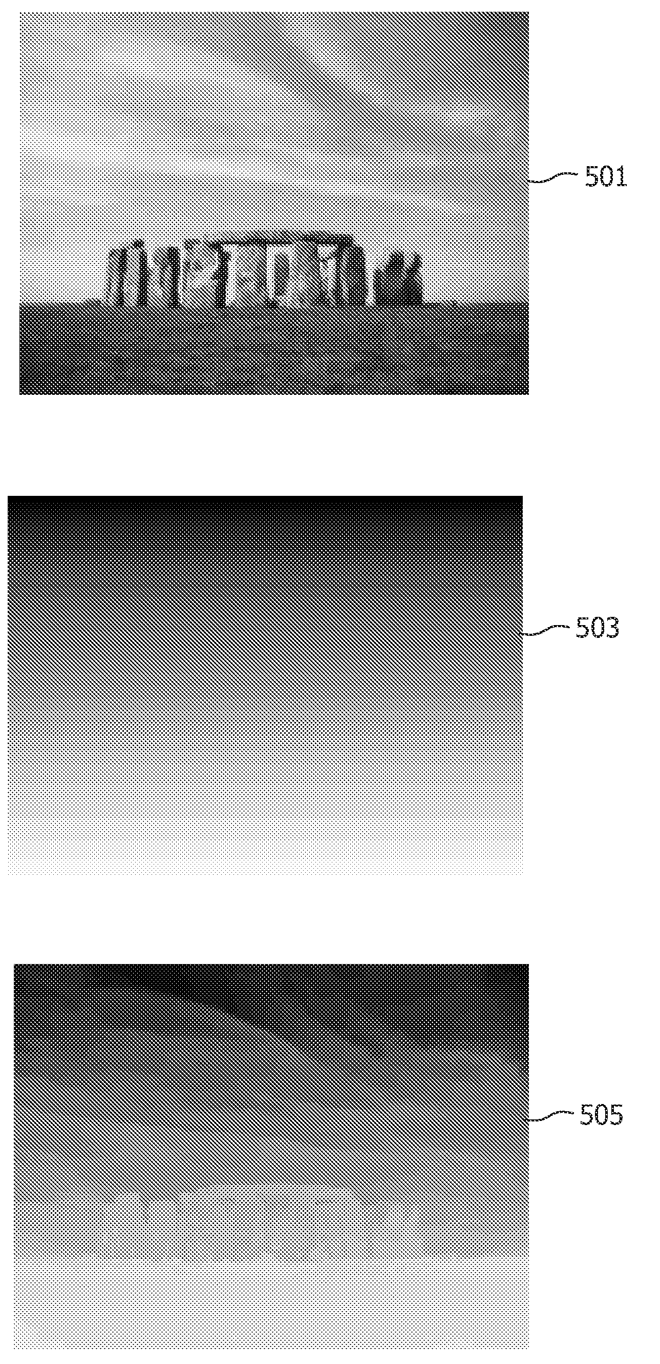
[0054]The image processing unit comprises a first processing unit 101 which is arranged to generate a depth indication map for an image. The image may be, for example, a digital picture or an image of a video sequence. The depth indication map comprises depth information data for the image, and specifically may comprise relative depth information for different regions of the image.

[0055]The depth indication map may comprise information on an estimated relative or absolute depth of different regions or picture elements, also referred to as pixels, of the image. As such, the depth indication map may be a depth map with depth data for different pixels indicating an absolute depth or a relative depth with respect to other picture elements or objects. For example, the depth indication map may comprise a value for each pixel indicating a depth level to which the pixel belon...


PUM


Abstract

An image processing unit comprises a first processing unit (101) which generates a depth indication map for an image. The depth indication map may be, for example, an image object separation mask or a predetermined depth profile or background depth map. A second processing unit (103) generates a modified depth indication map by filtering the depth indication map in response to image characteristics of the image. The image adaptive filtering may, for example, provide a more accurate separation mask and / or may modify the predetermined depth profile to reflect the specific image. A third processing unit (105) generates an image depth map for the image in response to the modified depth indication map. The image depth map comprises data representing a depth of at least one image region of the image. The invention leads to the generation of an improved depth map for an image.

Description

FIELD OF THE INVENTION[0001]The invention relates to the generation of a depth map for an image and in particular, but not exclusively, to the generation of a depth map for a digital image comprising background and salient image objects.BACKGROUND OF THE INVENTION[0002]In recent years, the digitalization of images has become increasingly important for storage, manipulation, and distribution purposes. Furthermore, the digitalization of images allows complex manipulations and processing which provides opportunities not previously available. For example, in recent years significant research has been undertaken to provide algorithms for extracting depth information from images. Such depth information may provide three-dimensional (3D) information obtained from a two-dimensional (2D) image. Such 3D information may be used in many applications and may, for example, assist in automatic annotation of images. As another example, the 3D information may be used to generate enhanced images such...

Claims


Application Information

Patent Timeline
Patent Type & Authority Applications(United States)
IPC IPC(8): G06K9/46G06K9/34
CPCG06T2207/20012G06T7/0051G06T7/50
Inventor BOUGHORBEL, FAYCAL
Owner KONINKLIJKE PHILIPS ELECTRONICS NV
Learn More