Piezoelectric ceramic composition and piezoelectric part

a technology of piezoelectric and ceramics, applied in piezoelectric/electrostrictive/magnetostrictive devices, basic electric elements, generators/motors, etc., can solve the problems of difficult to obtain strong ceramic using lead titanate, pt or pd, and expensive refractory noble metals, etc., to achieve satisfactory piezoelectricity, the effect of resisting reflow heating treatmen

Inactive Publication Date: 2010-02-18
MURATA MFG CO LTD
View PDF5 Cites 0 Cited by
  • Summary
  • Abstract
  • Description
  • Claims
  • Application Information

AI Technical Summary

Benefits of technology

[0022]The main composition of the piezoelectric composition stated above is represented by the general formula of [(Pb1-x-yCaxSry){Ti1-z(Zn1 / 2W1 / 2)z}O3], where x, y, and z satisfy 0≦x≦0.2 (preferably 0≦x≦0.15), 0≦y≦0.2 (preferably 0≦y≦0.1), 0.1≦x+y≦0.2, and 0.04≦z≦0.1. Therefore, it is possible to fire the piezoelectric ceramic composition at low temperature equal to or lower than 1100° C., to have a high Curie point equal to or higher than 300° C. and thereby realize resistance to a reflow heating treatment using a lead-free solder, and to obtain satisfactory piezoelectricity.
[0023]Since the piezoelectric ceramic composition can be fired at the low temperature equal to or lower than 1100° C., there is no need to use a high-melting noble metal such as Pd or Pt as an internal electrode material but a conductive material having a relatively low melting point such as a Ag—Pd alloy mainly containing Ag can be used. In other words, it is possible to obtain a dense piezoelectric ceramic even if the composition is fired at the low temperature equal to or lower than 1100° C. and reduce manufacturing cost.
[0024]Moreover, since a high Curie point Tc equal to or higher than 300° C. can be secured, the piezoelectric ceramic composition can resist the lead-free solder reflow heating treatment and a piezoelectric part suitable for such a reflow heating treatment can be realized.
[0025]The piezoelectric part using this piezoelectric ceramic composition can secure satisfactory piezoelectricity, including an electromechanical coupling factor kp equal to or higher than 15% and a mechanical quality factor Qm equal to or higher than 60. As for the temperature characteristics of resonance frequency, an absolute value |frTC| of a temperature rate of change based on +20° C. (hereinafter, simply referred to as the “temperature rate of change |frTc|”) in a temperature range from −20° C. to +80° C. can be suppressed to be equal to or lower than 80 ppm / ° C. It is, therefore, possible to secure satisfactory temperature characteristics.
[0026]The piezoelectric ceramic composition contains the Mn component in an amount of 0.05 weight part to 1.0 weight part calculated in terms of MnCO3 with respect to 100 weight parts of the main component. It is thereby possible to greatly improve the mechanical quality factor Qm in addition to the above-stated advantages effects.

Problems solved by technology

It has a small number of pores and it is difficult to obtain strong ceramic using this lead titanate.
Furthermore, expensive refractory noble metals such as Pt or Pd were initially used as an internal electrode material forming each conductive layer.
However, the low-cost metals normally have a low melting point.

Method used

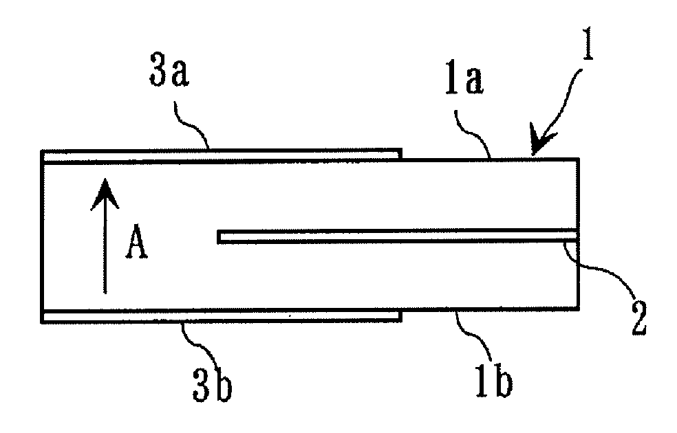

Image

  • Piezoelectric ceramic composition and piezoelectric part
  • Piezoelectric ceramic composition and piezoelectric part

Examples


example 1

[0070]As ceramic raw materials, Pb3O4, CaCO3, SrCO3, TiO2, ZnO, and WO6 were prepared.

[0071]The ceramic raw materials were weighed so as to obtain component composition of a final composition as shown in Table 1. Next, these weighed materials were put into the ball mill containing partially-stabilized zirconia, and sufficiently wet blended for about 16 hours using pure water as a solvent, thereby producing a slurry.

[0072]After drying this slurry, it is calcined at a temperature of 900° C. under oxidizing atmosphere, thereby obtaining a calcined compact. After shredding (grinding) the calcined compact, polyvinyl alcohol resin serving as an organic binder was added to the shredded calcined compact, and the binder-added calcined compact were put again into the ball mill containing partially-stabilized zirconia and wet milled for about 16 hours, thereby producing a second slurry. The second slurry was formed into sheets by the doctor blade method, thereby producing ceramic green sheets....

example 2

[0106]MnCO3 was prepared in addition to the ceramic raw materials described in Example 1.

[0107]Next, Pb3O4, CaCO3, SrCO3, TiO2, ZnO, and WO6 were weighed so as to obtain main component composition of (Pb0.8Ca0.1Sr0.1) {Ti0.95 (Zn1 / 2W1 / 2)0.05}O3. The MnCO3 was weighed so as to have a content shown in Table 3 with respect to 100 weight parts of the main component.

[0108]Thereafter, samples 31 to 35 were produced by similar method and procedures to those of Example 1. The firing temperature was set to 1100° C. for all of the samples 31 to 35.

[0109]Next, the sintered density, electromechanical coupling factor kp by thickness longitudinal oscillation, mechanical quality factor Qm, Curie point Tc, and temperature rate of change |frTC| of an resonance frequency of each of the samples 31 to 35 were measured by similar method and procedures to those of Example 1.

[0110]The Table 3 shows constituent components and firing temperatures of the samples 31 to 35, and Table 4 shows measurement result...


PUM

PropertyMeasurementUnit
temperatureaaaaaaaaaa
Curie points Tcaaaaaaaaaa

Abstract

A piezoelectric ceramic composition contains main components represented by a general formula of [(Pb1-x-yCaxSry){Ti1-z(Zn1 / 2W1 / 2)z}O3], and x, y, and z satisfy 0≦x≦0.2 (preferably 0≦x≦0.15), 0≦y≦0.2 (preferably 0≦y≦0.1), 0.1≦x+y≦0.2, and 0.04≦z≦0.1. It is also preferable that the piezoelectric ceramic composition contains 0.05 weight part to 1.0 weight part of a Mn component calculated in terms of MnCO3 with respect to 100 weight parts of the main component. A piezoelectric part includes a piezoelectric ceramic element that is formed by the piezoelectric ceramic composition. It is thereby possible to realize a piezoelectric ceramic composition that can be fired at low temperature, that has a high Curie point Tc resistant to a reflow heating treatment on a lead-free solder, and that exhibits satisfactory piezoelectricity, and a piezoelectric part using this piezoelectric ceramic composition.

Description

[0001]This is a continuation of application Serial No. PCT / JP2008 / 027329, filed Apr. 15, 2009, which is incorporated herein by reference.TECHNICAL FIELD[0002]The present invention relates to a piezoelectric ceramic composition and a piezoelectric part. More specifically, the present invention relates to a lead titanate-based piezoelectric ceramic composition that can be low-temperature fired and a piezoelectric part using the same.BACKGROUND ART[0003]Lead titanate (PbTiO3) having a perovskite structure (general formula ABO3) is ferroelectric and suited as a piezoelectric material because of its exhibition of piezoelectricity. It has a small number of pores and it is difficult to obtain strong ceramic using this lead titanate. Research and development of a method to obtain a dense piezoelectric ceramic composition by substituting an element such as Ca, Sr, Zn or W for a part of Pb or Ti or by adding various types of components to the lead titanate was undertaken, and practicable appl...

Claims


Application Information

Patent Timeline
Patent Type & Authority Applications(United States)
IPC IPC(8): C04B35/109H01L41/047H01L41/187H01L41/22H01L41/39
CPCC04B35/472C04B2235/3208C04B2235/3213C04B2235/3258C04B2235/3262H01L41/187C04B2235/6025C04B2235/768C04B2235/77H01L41/083C04B2235/3284H10N30/50H10N30/853
Inventor KIMURA, MASAHIKO
Owner MURATA MFG CO LTD
Why Eureka
Try Eureka