High-Resolution Ion Chamber

a high-resolution, ion chamber technology, applied in the direction of instruments, calibration apparatus, optical radiation measurement, etc., can solve the problem of difficult to construct small ionization detectors

Active Publication Date: 2010-02-18
STANDARD IMAGING
View PDF4 Cites 8 Cited by
  • Summary
  • Abstract
  • Description
  • Claims
  • Application Information

AI Technical Summary

Benefits of technology

[0006]The present invention provides an ionization chamber having two measurement volumes, one substantially surrounding the other, either or both of which may be larger than the desired measured radiation field. By using the readings from the two chambers of different sizes, it is possible to detect and or correct for the partial volume effects.
[0010]It is thus a feature of at least one embodiment of the invention to permit the construction of nested ionization detectors without adversely changing the energy spectrum of the radiation beam such as may unacceptably change the calibration of either detector.
[0012]It is thus a feature of at least one embodiment of the invention to provide for simple fabrication of the outer chamber such as from easily machined or molded polymer materials.
[0014]It is thus a feature of at least one embodiment of the invention to minimize the effects of the angle of the measured beam on the relationship between the measurements of the ionization chambers used for the partial volume correction.
[0016]It is thus a feature of at least one embodiment of the invention to minimize the effect of the angle of the radiation beam on the measurements.
[0024]It is thus a feature of at least one embodiment of the invention to provide for improved correction for partial volume effects through the use of an additional chamber.

Problems solved by technology

It is difficult to construct ionization detectors that are small enough to avoid partial volume effects while providing desired sensitivity.

Method used


Image

  • High-Resolution Ion Chamber
  • High-Resolution Ion Chamber
  • High-Resolution Ion Chamber

Examples


Embodiment Construction

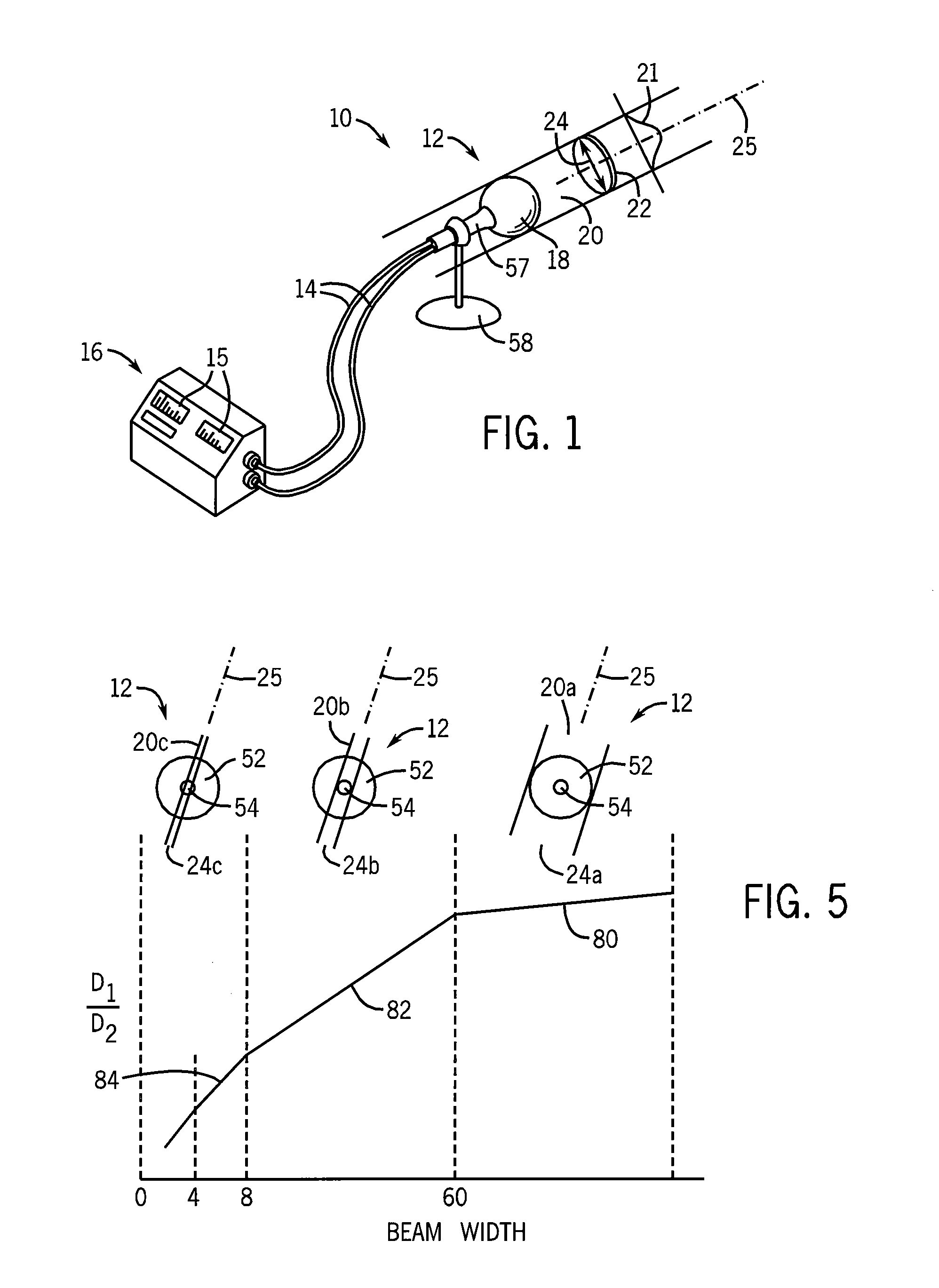
[0032]Referring now to FIG. 1, the present invention provides an ion chamber system 10 including a detector assembly 12 connected by electrical cables 14 to an electrometer unit 16. In use, a detector head 18 of the detector assembly 12 may be positioned within a radiation beam 20 to be exposed to the beam 20. As will be described below, the detector head 18 contains two independent ionization detectors one within the other and each attached to a separate cable 14. In one embodiment, the electrometer unit 16 may provide for two displays 15 each outputting a dose measurement received from one of the ionization detectors.

[0033]Generally, the radiation beam 20 will have a cross-sectional area 22 taken perpendicular to an axis 25 of the beam 20 along which the radiation propagates. For beams 20 with cross-sectional areas 22, a beam width 24 may be defined related to the cross-sectional area 22.

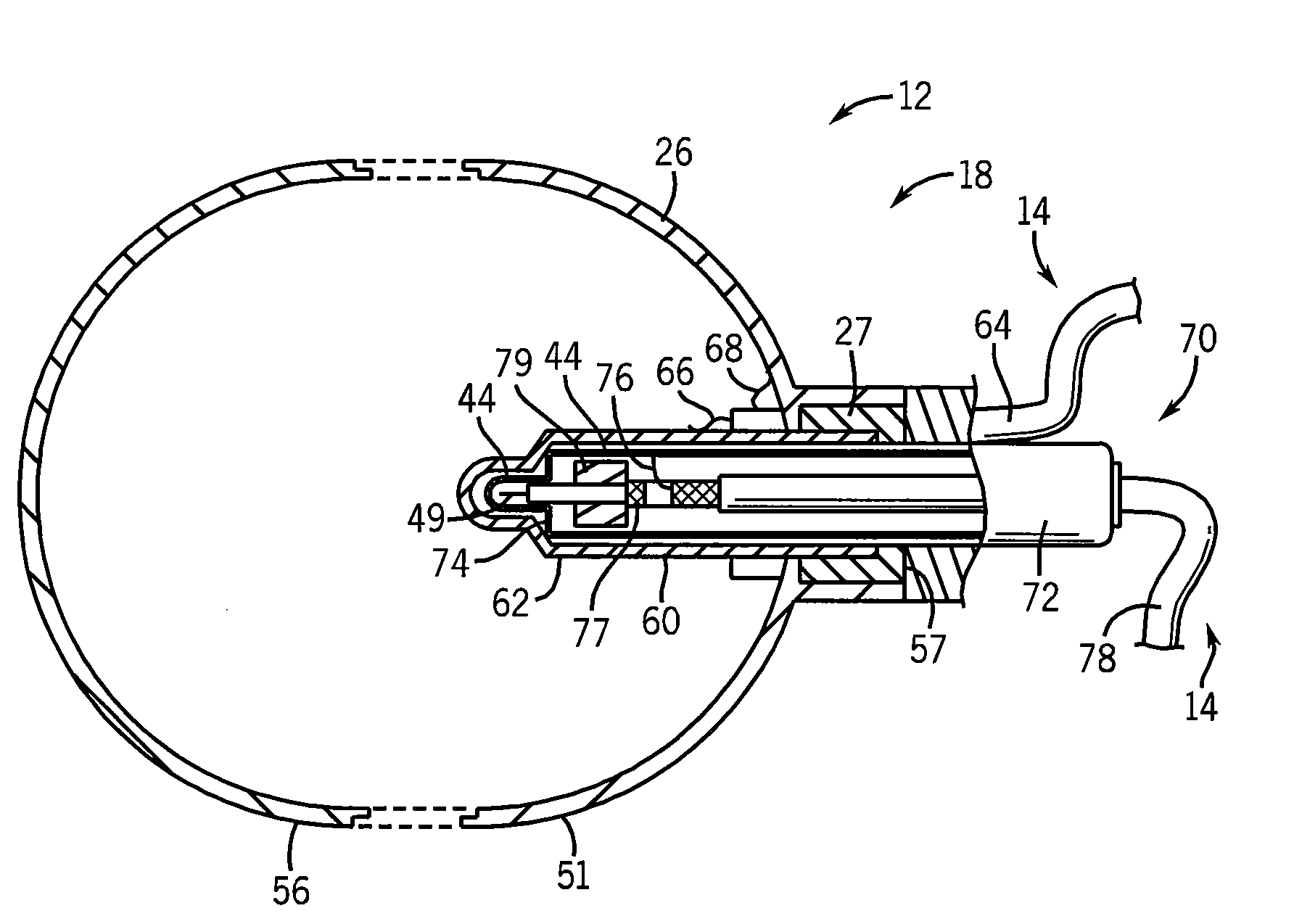
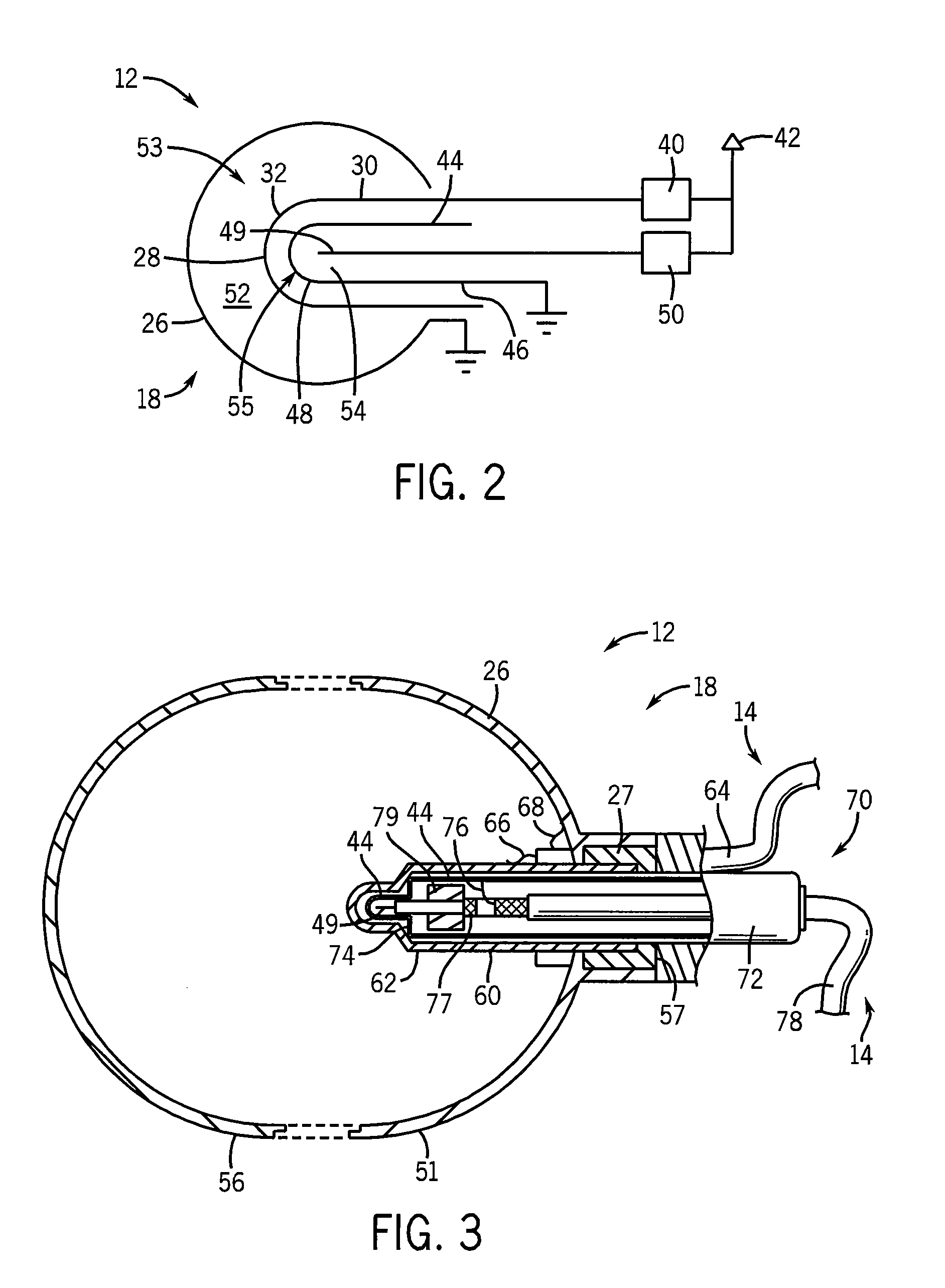
[0034]Referring now to FIG. 2, the detector head 18 of the detector assembly 12 may provide a ...


PUM


Abstract

Nested ionization chambers provide independent measurements of a radiation beam that does not fully irradiate the volume of one or both chambers. By mathematically combining these independent measurements, partial volume effects caused by a change in ionization detector calibrations when the full detector volume is not irradiated by the radiation beam, may be decreased, providing more accurate measurement of extremely small radiation beams.

Description

CROSS-REFERENCE TO RELATED APPLICATIONS[0001]This application claims priority from previously filed U.S. Provisional Patent Application Ser. No. 61 / 089,751 filed on Aug. 18, 2008 hereby incorporated by reference in its entirety.BACKGROUND OF THE INVENTION[0002]External beam radiation therapy systems provide beams of high-energy directed into a patient to treat tumors or the like. The size, location, angle and intensity of the beams are determined by a treatment plan based upon the precise measurement of the dose to be delivered to the patient to provide for precise control of the dose to the patient.[0003]Quantitative accuracy is ensured by periodic calibration of the machine using radiation detectors and phantoms to determine the relationship between the control settings of the machine and actual dose. One type of radiation detector is an ionization chamber in which electrodes are placed on opposite sides of a volume of gas. The gas is ionized by the radiation passing through the c...

Claims


Application Information

Patent Timeline
IPC IPC(8): G01D18/00G01T1/20G01T1/24G01T1/185G01T1/00
CPCG01T1/185
Inventor DEWERD, LARRY A.HOOTEN, BRIAN D.NEUMUELLER, EDWARD W.
Owner STANDARD IMAGING
Why Eureka
Try Eureka