
Network connection apparatus and a method thereof

a network connection and network technology, applied in the field of network connection apparatus, can solve the problems of network management work becoming more complicated, affecting the reliability of network connections,

Inactive Publication Date: 2010-02-11
NEC CORP
View PDF3 Cites 16 Cited by
  • Summary
  • Abstract
  • Description
  • Claims
  • Application Information

AI Technical Summary

Benefits of technology

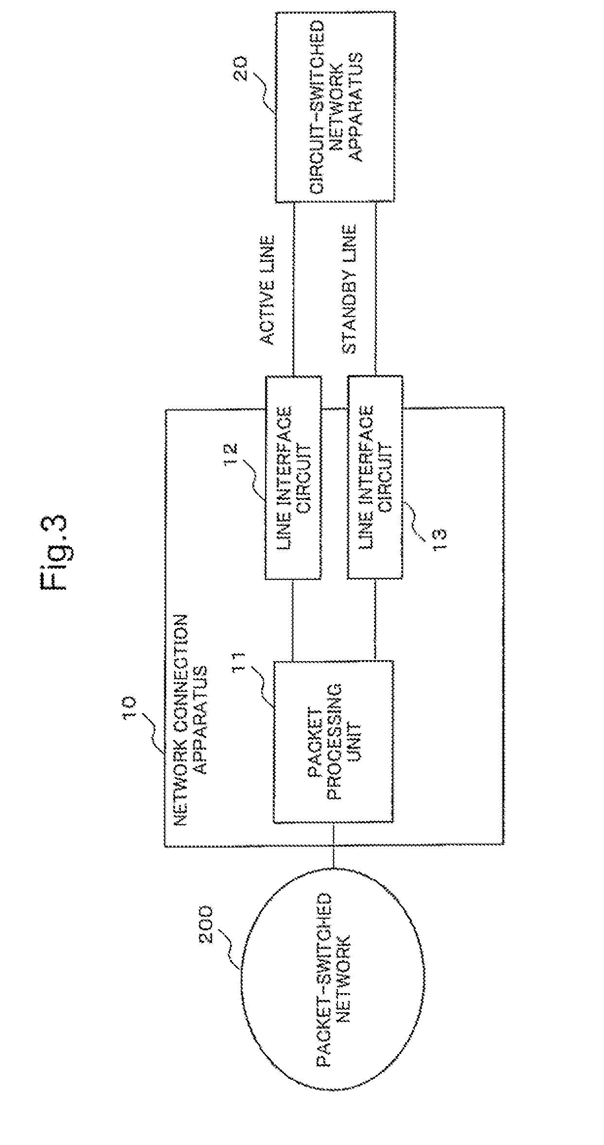
The present invention provides a network connection apparatus that can operate appropriately even when using a MAC address for routing in a network connection. The apparatus includes a redundant configuration of two transmission lines and two line interface circuits that convert data used in a circuit-switched network and a packet used in a packet-switched network. The apparatus also includes a packet processing unit that sends and receives packets between the line interface circuits and the packet-switched network. The apparatus can transmit a packet received from the packet-switched network to both line interface circuits and acquire the packet when the destination MAC address coincides with the first or second MAC address of the redundant configuration. The invention allows for efficient network connection and reliable data transmission.

Problems solved by technology

Therefore, network management works are becoming more complicated and the extension of facilities itself in the mobile backhaul area is also becoming in a difficult situation.
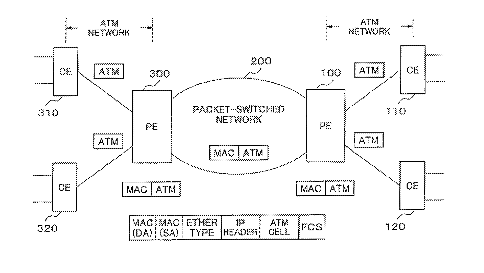
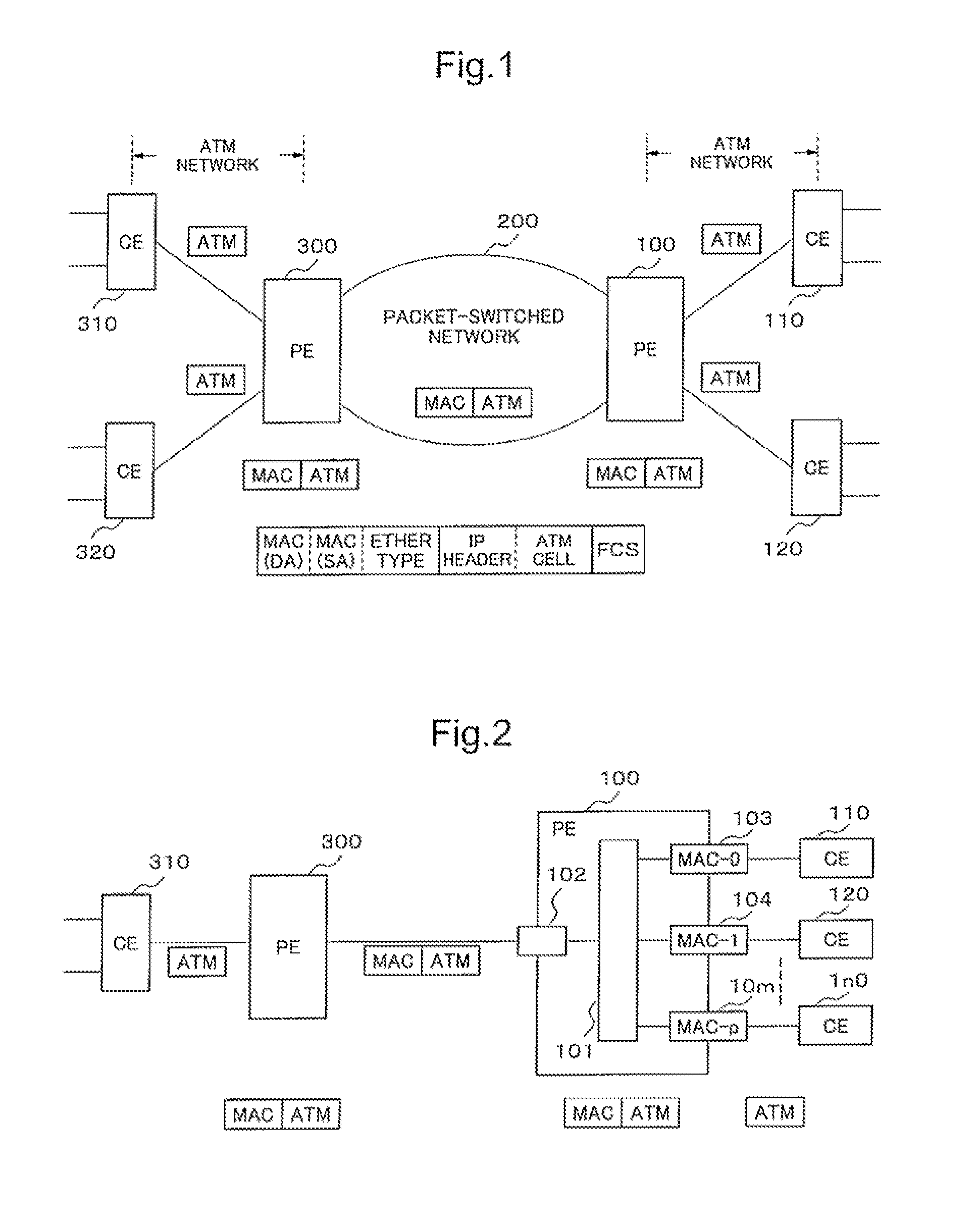
However, there is a problem to be settled in order to construct a system which transmits data generated by the existing facilities of TDM / ATM technology on the packet-switched network while keeping existing facilities as they are.
The problem is caused by difference in a concept of network reliability between the packet-switched network and the circuit-switched network.
However, when the APS function is introduced into the system which transmits data used in the circuit-switched network on the packet-switched network, there is a problem that the APS function does not operate normally due to a concept of MAC address.

Method used


Image

  • Network connection apparatus and a method thereof
  • Network connection apparatus and a method thereof
  • Network connection apparatus and a method thereof

Examples


first exemplary embodiment

[0092]The exemplary embodiment in detail will be described.

[0093]FIG. 4 is a block diagram showing a structure of the network connection apparatus according to a first exemplary embodiment.

[0094]PE (Provider Edge) 100 which is a network connection apparatus of this exemplary embodiment includes a packet interface circuit 102, an ATM interface circuit 103, an ATM interface circuit 104 and a packet processing unit 101 as main components. The packet interface circuit 102 interfaces with the packet-switched network (not shown). Each of the ATM interface circuit 103 and the ATM interface circuit 104 accommodates an ATM line connected to an ATM apparatus (not shown) as CE (Customer Edge).

[0095]The ATM line accommodated in the ATM interface circuit 103 is assumed as an active ATM line and the ATM line accommodated in the ATM interface circuit 104 is assumed as a standby ATM line of the redundancy configuration of “1+1” basis. Therefore, the ATM interface circuit 103 is an active side ATM i...

second exemplary embodiment

[0235]Next, a network connection apparatus according to a second exemplary embodiment of the present invention will be described with reference to FIG. 18.

[0236]FIG. 18 is a block diagram showing a configuration of an ATM (Asynchronous Transfer Mode) interface circuit of the network connection apparatus according to the second exemplary embodiment.

[0237]In the second exemplary embodiment, only an operation of the APS function for upstream direction is different from it of the first exemplary embodiment, and an operation for downstream direction is the same as the operation of the first exemplary embodiment.

[0238]In the first exemplary embodiment, it has been configured for the APS function of upstream direction that the APS control table 1013 provided in the packet processing unit 101 was referred and only packets received from the active ATM line were handled to be transmitted to the packet-switched network.

[0239]On the other hand, the APS control table 1015 provided in the packet ...

third exemplary embodiment

[0255]FIG. 21 is a block diagram showing a configuration of a network connection apparatus according to a third exemplary embodiment.

[0256]The third exemplary embodiment has a configuration equipped with TDM (Time Division Multiplex) interface circuits 103-1 and 104-1 corresponding to an active TDM line and a standby TDM line respectively. The TDM interface circuit is used when the network between the network connection apparatus and the apparatus located in the lower hierarchy is a TDM (Time Division Multiplex) network.

[0257]The TDM interface circuit includes a TDMoP (TDM over packet) circuit which generates a packet based on TDM data transmitted from the TDM network, and the network connection apparatus transmits the generated packet to the packet-switched network. On the other hand, the TDMoP circuit disassembles a packet received from the packet-switched network, extracts TDM data included in the received packet, and transmits the extracted TDM data to the TDM network.

[0258]Othe...


PUM


Abstract

A network connection apparatus includes, a pair of line interface circuits which accommodates each transmission line provided to interface with the circuit-switched network, composes an active line and a standby line of the redundant configuration, and mutually converts data used in the circuit-switched network and a packet used in the packet-switched network; and a packet processing unit which interfaces with the packet-switched network and performs a sending and receiving process of the packet between the line interface circuit and the packet-switched network. The packet processing unit transmits the packet received only from the line interface circuit of the active line to the packet-switched network, and transmits the packet received from the packet-switched network to both of the line interface circuits of the active line and the standby line. The line interface circuit acquires the packet transmitted from the packet processing unit when a destination MAC address included in the packet coincides with a first MAC address which is given to own line interface circuit or a second MAC address which is given to the other line interface circuit of pair for the redundant configuration.

Description

[0001]This application is based upon and claims the benefit of priority from Japanese patent application No. 2008-204244, filed on Aug. 7, 2008 the disclosure of which is incorporated herein in its entirety by reference.TECHNICAL FIELD[0002]The present invention relates to a network connection apparatus and a method thereof, and in particular, relates to a network connection apparatus which is provided with an APS (Automatic Protection Switching) function and interconnects a circuit-switched network, which includes an ATM (Asynchronous Transfer Mode) network and a TDM (Time Division Multiplex) network, and a packet-switched network.BACKGROUND ART[0003]In recent years, information and telecommunications networks based on IP (Internet Protocol) technology are rapidly spread and widely used. In particular, the information and telecommunications network using Ethernet (registered trademark) is spreading rapidly as the wide area Ethernet (registered trademark) service. And, the network c...

Claims


Application Information

Patent Timeline
Patent Type & Authority Applications(United States)
IPC IPC(8): G06F11/00H04L12/66H04L12/46H04L45/24H04L45/586
CPCH04L12/66H04L12/6402
Inventor YOSHIMURA, MIKIHIRO
Owner NEC CORP
Learn More