
Stacked secondary battery and method of manufacturing the same

a secondary battery and stacked technology, applied in the direction of batteries, sustainable manufacturing/processing, cell components, etc., can solve the problem of difficult to accurately punch out the electrode by a single punching operation, and achieve excellent charging/discharging characteristics

Inactive Publication Date: 2010-02-04
NEC ENERGY DEVICES LTD
View PDF3 Cites 42 Cited by
  • Summary
  • Abstract
  • Description
  • Claims
  • Application Information

AI Technical Summary

Benefits of technology

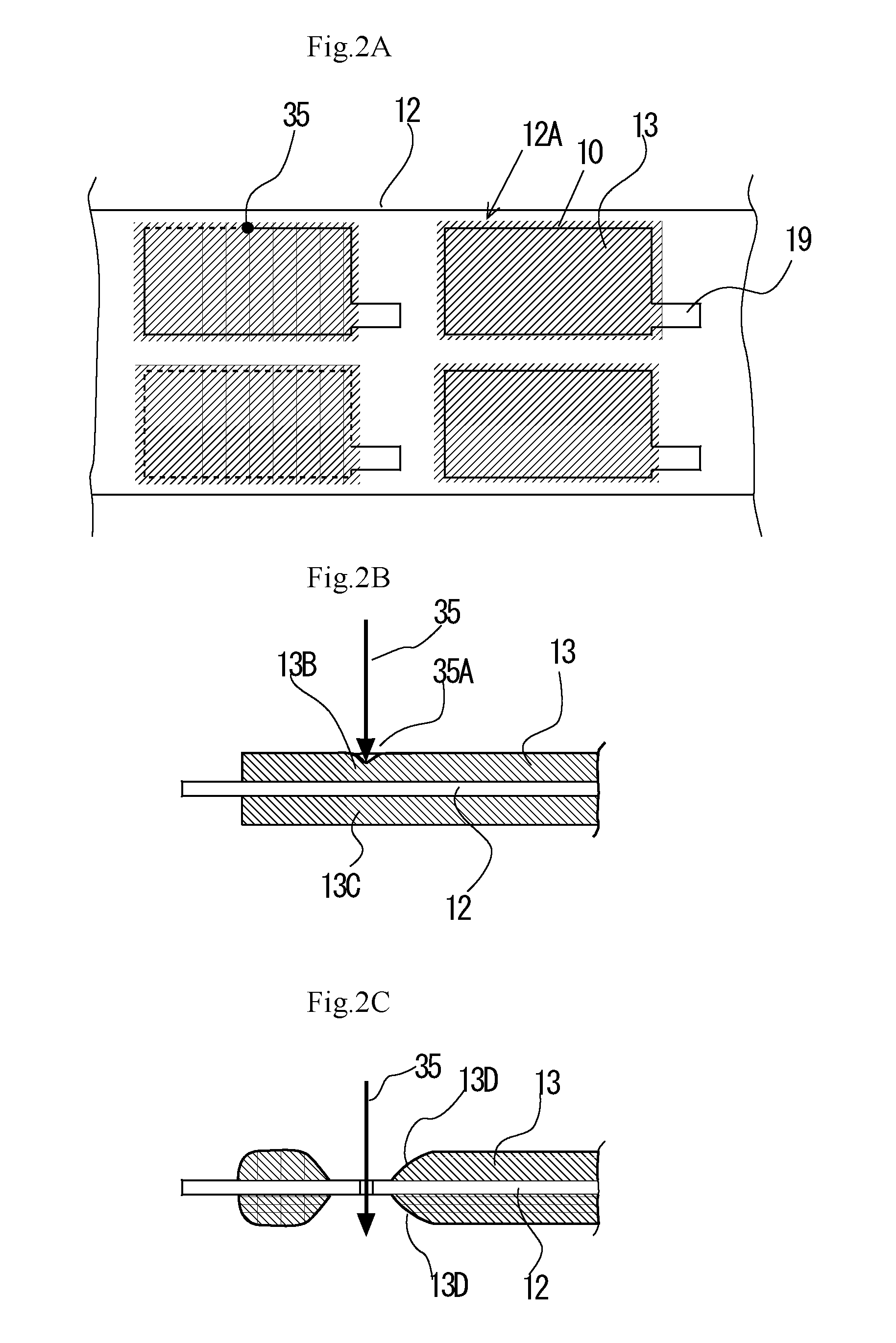
[0023]In a stacked secondary battery formed by laying plate-shaped positive electrodes and plate-shaped negative electrodes one on the other by way of separators according to the present invention, a collector is disposed at the front end of the end facet of each of the positive electrodes or the negative electrodes as viewed in a direction orthogonal relative to the stacking direction and has an active substance layer formed on the collector by applying slurry of particles of an active substance with a gap separating it from the front end or the active substance layer is made to show a thickness varying from the front end of the collectors toward the inside. Thus, according to the present invention, it is possible to provide a stacked secondary battery in which the cut end facet of each of the electrodes is smooth and the active substance adheres to the collector with large adhering force so as to make the battery show excellent charging / discharging characteristics. Additionally, the active substance of the battery is prevented from coming off to a large extent because of the one or two molten and solidified sections formed in an outer peripheral part of the active substance layer of each electrode.

Problems solved by technology

Additionally, such a punching process provides an advantage that electrode can be cut out to show a predetermined profile in a short period of time, it is accompanied by a problem that it is difficult to accurately punch out the electrode by a single punching operation because the part thereof where the active substance is applied and the part thereof where no active substance is applied show a difference of thickness.
For a stacked secondary battery such as a stacked lithium ion battery in which plate-shaped positive electrodes and plate-shaped negative electrodes are laid one on the other by way of separators, it is a problem to make the battery show excellent charging / discharging characteristics without increasing self discharges that take place due to the positive electrode active substance and / or the negative electrode active substance coming off from the positive electrodes and / or the negative electrodes, whichever appropriate.

Method used


Image

  • Stacked secondary battery and method of manufacturing the same
  • Stacked secondary battery and method of manufacturing the same
  • Stacked secondary battery and method of manufacturing the same

Examples


example 1

[0056]Slurry was prepared from 63 mass portions of a lithium manganese complex oxide having a number average particle diameter of 15 micrometer, 4.2 mass portions of acetylene black having a number average particle diameter of 7 micrometer, 2.8 mass portions of polyvinylidene fluoride and 30 mass portions of N-methyl-2-pyrrolidone.

[0057]The slurry was then applied to an aluminum foil having a thickness of 20 micrometer-thick and a width of 150 mm-wide that is used for collector intermittently across the entire width of the foil to produce 20 mm-long unapplied parts and 130 mm-long applied parts. Then, the slurry was dried to produce a 180 micrometer-thick positive electrode active substance layer.

[0058]A laser beam was irradiated onto the aluminum foil by means of a YAG laser of a laser wavelength of 1,060 nm under irradiation conditions including a spot diameter of 12 micrometer, a laser output of 20 W and a laser overlapped frequency of 20 kHz to 100 kHz so as to form an electrode...

example 2

[0060]Positive electrodes were produced as in Example 1 except that a relative moving speed of 40 mm / sec of the laser beam and the positive electrode active substance layer was used to cut the aluminum foil. A photographic image of the cross section of an obtained positive electrode was taken by an optical microscope. FIG. 4 shows the obtained image.

example 3

[0063]Slurry was prepared from 49 mass portions of graphite having a number average particle diameter of 10 micrometer, 0.5 mass portions of acetylene black having a number average particle diameter of 7 micrometer, 3.5 mass portions of polyvinylidene fluoride and 47 mass portions of N-methyl-2-pyrrolidone.

[0064]The slurry was then applied to a copper foil having a thickness of 10 micrometer-thick and a width of 150 mm-wide that is used for collector intermittently across the entire width of the foil to produce 20 mm-long unapplied parts and 130 mm-long applied parts. Then, the slurry was dried to produce a 112 micrometer-thick negative electrode active substance layer.

[0065]A laser beam was irradiated twice onto the aluminum foil by means of a YAG laser of a laser wavelength of 1,060 nm under irradiation conditions including a spot diameter of 12 micrometer and a laser output of 20 W so as to form an electrode draw-out terminal having a width of 13 mm and a length of 15 mm on each ...


PUM

PropertyMeasurementUnit
number average particle diameteraaaaaaaaaa
lengthaaaaaaaaaa

Abstract

A stacked secondary battery is formed by laying plate-shaped positive electrodes and plate-shaped negative electrodes one on the other by way of separators, wherein a collector is disposed at the front end of the end facet of each of the positive electrodes or the negative electrodes as viewed in a direction orthogonal relative to the stacking direction and has an active substance layer formed on the collector by applying slurry of particles of an active substance with a gap separating it from the front end or the electrode active substance layer is made to show a thickness varying from the front end toward the inside.

Description

CROSS-REFERENCE TO RELATED APPLICATIONS[0001]This application is based upon and claims the benefit of priority from prior Japanese Patent Application No. 2008-197773, filed Jul. 31, 2008, the entire contents of which are incorporated herein by reference.BACKGROUND OF THE INVENTION[0002]The present invention relates to a stacked secondary battery formed by sealing battery element including a multilayer structure prepared by laying flat plate-shaped positive electrodes and also flat plate-shaped negative electrodes one on the other by way of separators.[0003]Lithium ion batteries are being broadly employed for portable equipment designed to be driven by a battery such as mobile phones because lithium ion batteries have a large charge / discharge capacity. Additionally, there is a large demand for high efficiency secondary batteries that can find applications in the field of electric vehicles, electric bicycles, electric tools and power storages.[0004]Stacked batteries prepared by laying...

Claims


Application Information

Patent Timeline
Patent Type & Authority Applications(United States)
IPC IPC(8): H01M4/02H01M4/82H01M4/13H01M4/139H01M4/70H01M10/04
CPCH01M4/139H01M10/0413Y10T29/4911Y02E60/122Y02T10/7011H01M10/0525Y02E60/10Y02P70/50H01M10/0585H01M2220/10H01M2220/20Y02T10/70
Inventor INOSE, TSUYOSHIDAIDOJI, TAKAO
Owner NEC ENERGY DEVICES LTD
Learn More