
Image acquisition system

a technology of image acquisition and image, applied in the field of image acquisition systems, can solve the problems of inability to detect errors, inability to meet the design goals of existing imaging technology typically used in machine vision systems, and inability to meet the requirements of modern machine vision systems, so as to achieve the effect of reducing data management tasks, reducing latency, and improving image fidelity

Inactive Publication Date: 2010-02-04
METROVIDEO
View PDF11 Cites 13 Cited by
  • Summary
  • Abstract
  • Description
  • Claims
  • Application Information

AI Technical Summary

Benefits of technology

"The present invention is an image acquisition system that eliminates errors and delays in image processing by integrating various components into one dedicated machine architecture. This architecture allows for preliminary image processing operations in real-time, such as correcting hardware and scene errors, without burding the host processor. The system also includes a programmable imager controller that can change system parameters in real-time, without sacrificing data throughput. The system can acquire and transfer images faster than conventional systems, providing flexibility and high-speed control. Additionally, the system can acquire and transfer images asynchronously and independently of the host processor, further improving image fidelity and throughput."

Problems solved by technology

There is, however, a mismatch between the requirements of modern machine vision systems and the design goals of existing imaging technology typically used with machine vision systems.
With a new frame being transmitted every 1 / 60 second, missing lines and / or frames in such a system are tolerable because they are generally unnoticed by a human viewer.
Because errors that occur during image acquisition and transfer, such as dropped lines and frames, are only presented to a viewer for 1 / 60th of a second, and because the human eye acts as a time integrator, these intermittent errors are rarely perceptible to a human observer.
For example, if the machine vision system is looking for normal process variations in manufactured parts, any imaging errors can result in the inappropriate rejection of a part.
This leads to unnecessary part waste and an increase in the total costs of production.
Errors in an image acquisition system include imaging errors and processing errors.
Processing errors, such as dropped lines and frames, arise from errors that occur as image data travels from the camera to the host computing system.
Imaging errors arise in the camera itself or in the environment outside the camera.
Sensor errors typically arise from differences between photosensitive elements, (e.g., photosites in a charge-coupled device) that form part of the image acquisition system.
Scene errors are those errors that arise from incorrectly illuminating a scene.
Since ambient lighting conditions cannot be controlled to the same level of precision as that resolvable by a modern machine vision system, subtle variations in lighting levels or colors, due, for example, to aging of light sources, can degrade the performance of the machine vision system.
Unlike conventional image acquisition systems which obtain images either continuously or at regular intervals, machine vision systems can require images at unpredictable times. For example, in an automated inspection line, the objects to be inspected may not be spaced apart regularly enough on the conveyor belt to permit periodic image acquisition.
Consequently, a machine vision system does not have the luxury of knowing, in advance, when an image is to be received.
This reliance on a scarce resource such as the host processor results in latency periods during which image acquisition and transfer cannot occur because the host processor is busy performing other tasks.
These latency periods of uncertain duration make it difficult, if not impossible, for a machine vision system to repeatedly acquire an image on demand.
When the latency period becomes excessively long, collisions can occur in the data path as data from subsequent images arrives faster than data from previous images can be processed.
This results in lost or erroneous data.
The disadvantage of this method is that the dedicated memory becomes unavailable for use by other processing tasks, even when it is not being used for image transfer.
A disadvantage of this system type is that, when used in conjunction with a multithreaded computing environment, the complexity of programming this task becomes rapidly unmanageable.
This raises the problem of how to acquire an image only when an object to be inspected is in the camera's field of view or in a particular region within the camera's field of view.
These sensors, however, are typically difficult to interface reliably with the machine vision system.
Moreover, latency associated with the machine vision system can make it difficult to reliably position the object to be inspected in the correct region of the camera's field of view.
Further important constraints imposed by conventional image acquisition systems include the relatively fixed field of view, relatively fixed frequency of image capture, fixed and relatively low rate of image transfer to host computer memory (or relatively expensive transfer of image), and lack of data integrity, arising, for example, from gray scale errors due to several causes including pixel jitter and skew, or from lost data such as dropped lines and frames.
Additionally, current machine vision systems are relatively expensive to install and operate.
Another drawback of these systems is that they are unable to change the form of the acquired image data in real time, in other words, between each acquired frame or shot.
These custom systems are typically very expensive to acquire and very difficult to integrate with existing machine vision systems.

Method used


Image

  • Image acquisition system
  • Image acquisition system
  • Image acquisition system

Examples


Embodiment Construction

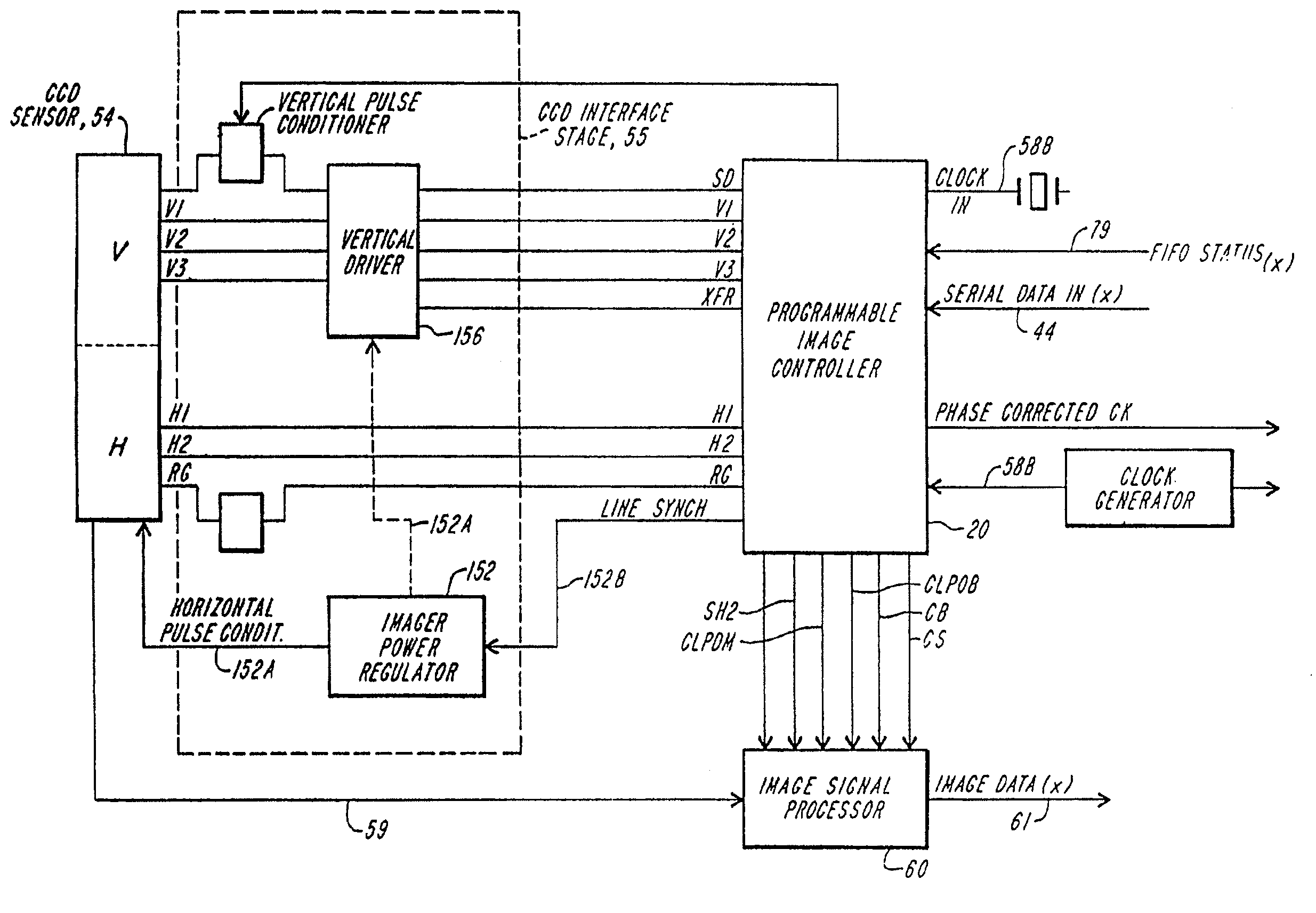
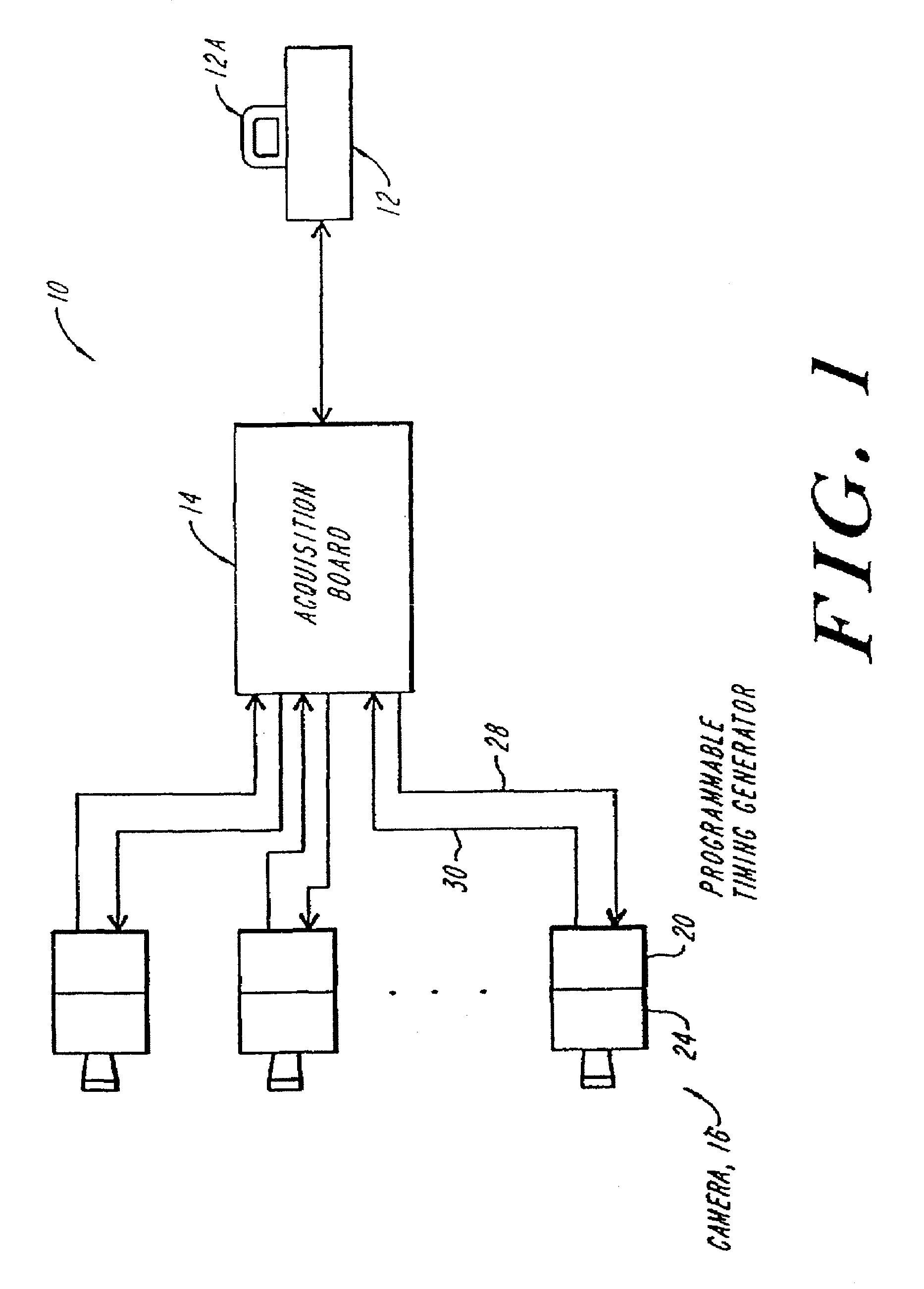
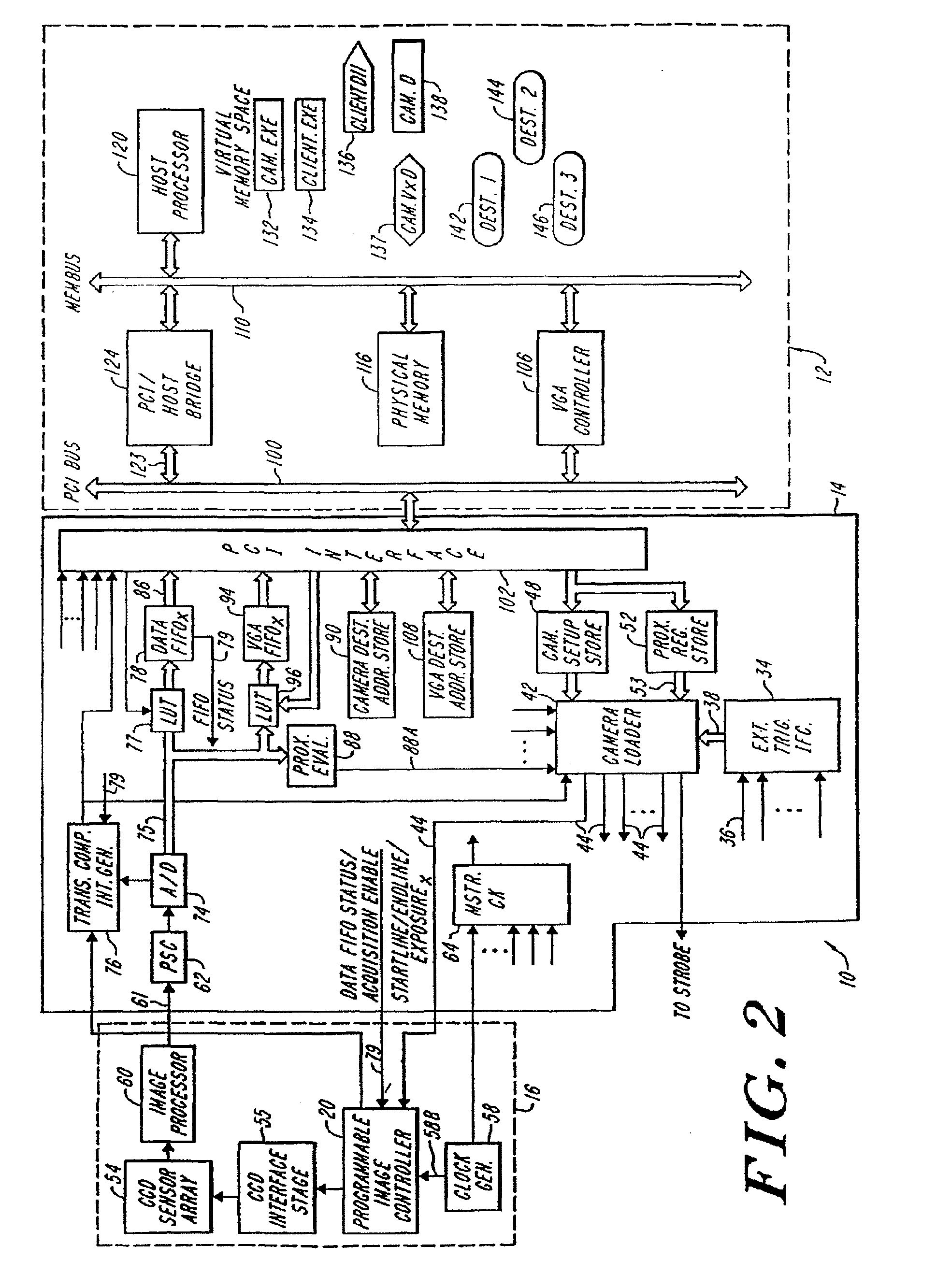
[0048]FIG. 1 is a schematic illustration of the image acquisition system 10 according to the teachings of the present invention. The illustrated system 10 includes a central or host computing system 12. The host computing system can be any conventional computing apparatus and can comprise a display monitor and a dedicated signal processor or can be a client signal processor which forms part of a larger area network, such as a LAN or WAN. The host computing system 12 is preferably in communication with an acquisition board 14, which in turn is coupled to one or more external image capturing devices 16, e.g., cameras. The acquisition board 14, although illustrated as being located outside of the host system 12, can form part of that system as will be appreciated by those of ordinary skill. Consequently, occasionally the combination of the two will be referred to as the host system. According to a preferred practice, the acquisition board is similar to a PCI bus card which interfaces w...


PUM


Abstract

An image acquisition system for machine vision systems decouples image acquisition from the transmission of the image to a host processor by using a programmable imager controller to selectively disable and enable the transmission of data to the host and by using a system of buffers to temporarily store image data pending allocation of memory. This enables the image acquisition system to acquire images asynchronously and to change the exposure parameters on a frame-by-frame basis without the latency associated with the allocation of memory for storage of the acquired image. The system architecture of the invention further permits interruption and resumption of image acquisition with minimal likelihood of missing data. Data throughput is further enhanced by transmitting to the host only that data corresponding to the region of interest within the image and discarding the data from outside of the region of interest at the camera stage.

Description

RELATED APPLICATIONS[0001]The current application is a continuation of Ser. No. 10 / 355,717, filed Jan. 31, 2003, which, in turn, is a continuation of Ser. No. 09 / 932,275 filed Aug. 16, 2001, which, in turn, is a continuation of Ser. No. 08 / 884,589 filed Jun. 27, 1997, now U.S. Pat. No. 6,282,462 which claims priority to U.S. Provisional Application No. 60 / 038,690, filed on Feb. 7, 1997 and the commonly-owned and U.S. Provisional Application 60 / 020,885, filed on Jun. 28, 1996. The entire contents of each of these applications and patents are hereby incorporated herein by reference.BACKGROUND OF THE INVENTION[0002]The present invention relates to image acquisition systems, and more particularly to image acquisition systems suitable for machine vision systems that capture and process optical images.[0003]Conventional image acquisition systems have been used for decades to acquire and process optical images. The conventional systems typically employ one or more video cameras that acquir...

Claims


Application Information

Patent Timeline
Patent Type & Authority Applications(United States)
IPC IPC(8): H04N5/04H04N5/76G06T1/00H04N5/232
CPCH04N5/232G06T1/0007G06F13/385H04L49/90G06F5/10
Inventor HOPKINS, T. ERIC
Owner METROVIDEO
Learn More