
Preconditioner

A technology of preprocessor and filter, applied in instruments, regulating electrical variables, high-efficiency power electronic conversion, etc., can solve the problem of input current deviating from ideal waveform, etc.

Inactive Publication Date: 2006-04-19
变压器线圈公司
View PDF0 Cites 0 Cited by
  • Summary
  • Abstract
  • Description
  • Claims
  • Application Information

AI Technical Summary

Problems solved by technology

The disadvantage of this scheme is that the ripple in the output voltage is fed back in the feedback loop, causing the input current of the SMPS to deviate from the ideal waveform

Method used


Image

  • Preconditioner
  • Preconditioner
  • Preconditioner

Examples


Embodiment Construction

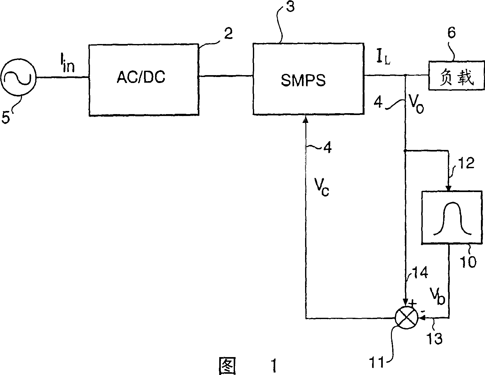
[0020] The pre-processor 1 shown in FIG. 1 comprises a rectifier 2 , a switched-mode power supply (SMPS) 3 including eg a pulse width modulator, and a feedback path 4 . The rectifier 2 receives the AC voltage (V AC ), preferably the mains voltage, and outputs a DC current I to the load 6 L . SMPS3 controls the current through the rectifier, reducing the harmonic current in this current. SMPS3 receives a voltage control signal from feedback path 4 (V c ).

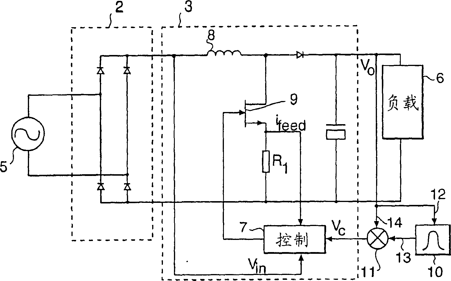
[0021] figure 2 An example of a preprocessor 1 is shown in more detail, comprising a rectifier bridge 2 with 4 diodes and a coil 8 , the SMPS 3 comprising a control block 7 . From figure 2 It can be clearly seen that the control block 7 drives the switch assembly 9 connected in series with the coil 8, and receives the measured value of the current i through the current detection resistor R1 feed . Furthermore, the feedback path 4 provides voltage feedback to the control block 7 .

[0022] According to the invention,...


PUM


Abstract

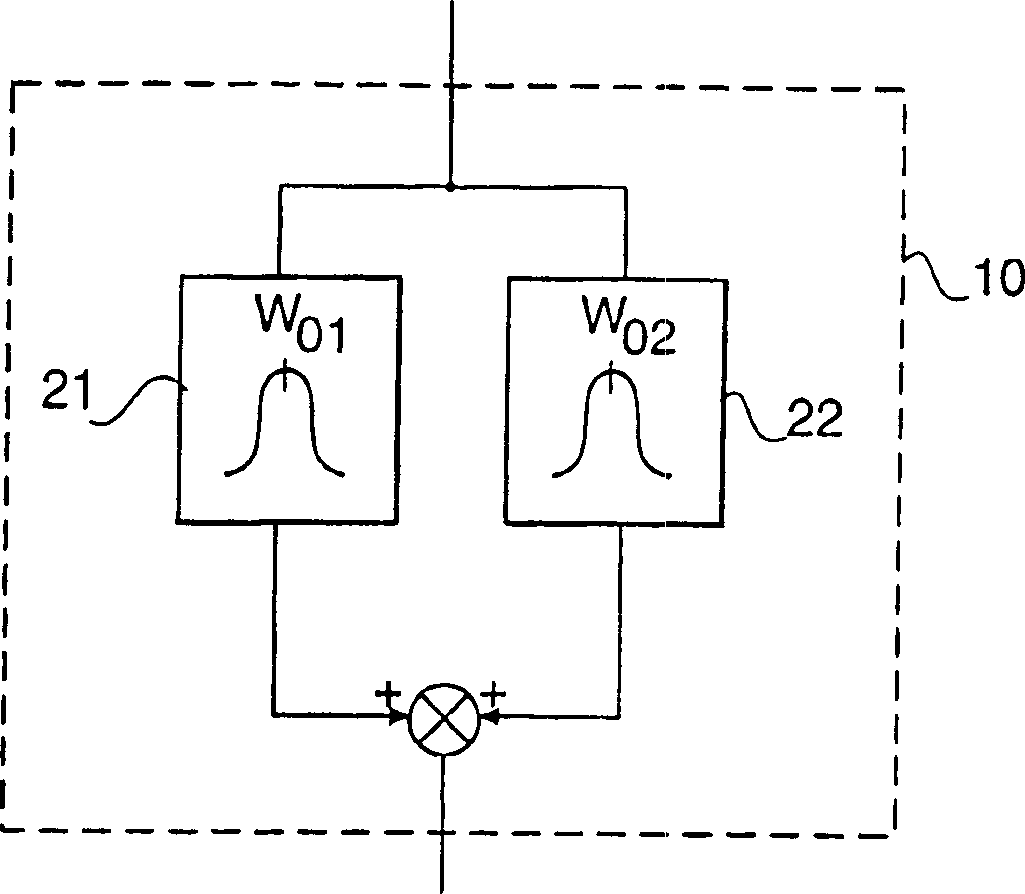
The present invention relates to a preconditioner having a rectifier, arranged to receive an AC voltage from a voltage supply and to deliver a DC voltage (V0) to a load, a switch mode power supply, arranged to control the current in the rectifier, and a control loop for feedback of the preconditioner output voltage (V0) to the switch mode power supply, said control loop having a bandwidth greater than the voltage supply frequency. The feedback loop comprises a bandpass filter with a band pass center frequency equal to twice the source frequency, which is connected to said output voltage, and means for generating a feedback signal based on the output voltage and an output signal from said bandpass filter, which feedback signal has reduced ripple around the passband. By eliminating the ripple in the voltage feedback loop, the preconditioner does not waste energy in an attempt to control this ripple, which is inherently present from the AC source.

Description

technical field [0001] The present invention relates to a pre-processor in which a rectifier is used to receive and rectify an AC voltage from a receiving voltage source, a switch-mode power supply is used to control the current in the rectifier, and a feedback path is used to convert the pre-processor output voltage to Feedback to a control block with a bandwidth equal to or greater than the voltage source frequency. Such a preprocessor can be easily implemented in any electronic device that meets the requirements of IEC61000-3-2, such as a TV set. Background technique [0002] To obtain a relatively stable DC output voltage from an alternating (usually sinusoidal) voltage source, the voltage is usually rectified with a rectifier bridge consisting of four diodes and a capacitor. Such a simple scheme produces an AC line input current with higher harmonics, and the higher the peak current, the shorter the charging time for the capacitor. This also leads to undesired losses ...

Claims


Application Information

Patent Timeline
Patent Type & Authority Patents(China)
IPC IPC(8): H02M7/5395H02M7/12H02M1/00H02M1/42H02M3/155H02M7/00H02M7/217
CPCH02M1/4225Y02B70/126Y02B70/10H02M3/155
Inventor H·R·德格罗特
Owner 变压器线圈公司
Learn More