
Servicing a plasma processing system with a robot

a plasma processing system and robot technology, applied in the direction of hollow article cleaning, manufacturing tools, arms, etc., can solve the problems of exacerbate the cleaning problem, non-volatile byproducts tend to tend to the plasma processing system, and expose the operator to hazardous duty

Active Publication Date: 2010-02-04
LAM RES CORP
View PDF35 Cites 10 Cited by
  • Summary
  • Abstract
  • Description
  • Claims
  • Application Information

AI Technical Summary

Benefits of technology

The invention is about a robot apparatus for a plasma processing system that can perform various service procedures, such as cleaning plasma chamber surfaces and removing byproduct deposits. The apparatus includes a platform, a docking probe, a robot arm, and a tool. The computer controls the robot arm to perform the service procedures. When the docking probe is connected to the docking port, the set of service procedures is performed by the tool. The invention allows for efficient and effective cleaning of the plasma chamber surfaces, which can improve the efficiency and reliability of the plasma processing system.

Problems solved by technology

In addition, servicing a plasma processing system may also expose an operator to hazardous duty (i.e., exposure to toxic gases or high temperatures, lifting heavy parts, etc.).
However, non-volatile byproducts will tend to be deposited on exposed surfaces within the plasma chamber or in the vacuum system.
The addition of metallic atoms from any of the sources mentioned above will often exacerbate the cleaning problem by formation of metallic, metal-organic compounds or metal oxides or mixtures thereof.
In addition, when these non-volatile byproducts eventually flake, they may subsequently increase the susceptibility of substrate defects, reduce the mean time between cleaning (MTBC), reduce yield, lead to unacceptable atomic surface contamination on the substrate, etc.
In operation, since substantially removing the byproducts may be time consuming, a plasma chamber is generally substantially cleaned only when, or preferably just before, particle contamination levels reach unacceptable levels, when the plasma processing system must be opened to replace a consumable structure (e.g., edge ring, optical access windows, etc.), or as part of scheduled preventive maintenance (PM).
However, customers may become complacent, or may instead only focus on maximizing equipment production time, and not on the performance of a thorough cleaning, which may amount to many thousands of dollars per hour in lost production time.
For examples, operators who are not properly monitored can create problems by modifying the cleaning method, such as by eliminating steps, doing a less than thorough job in cleaning deposit adhesion or attempting to improve the procedure without verifying compatibility or effectiveness with the recommended processes.
Subsequently, incomplete or incompatible cleaning can cause the plasma processing system to fail particle checks during substrate processing re-qualification or after processing has resumed, requiring additional unplanned maintenance and downtime.

Method used


Image

  • Servicing a plasma processing system with a robot
  • Servicing a plasma processing system with a robot
  • Servicing a plasma processing system with a robot

Examples


Embodiment Construction

[0028]The present invention will now be described in detail with reference to a few preferred embodiments thereof as illustrated in the accompanying drawings. In the following description, numerous specific details are set forth in order to provide a thorough understanding of the present invention. It will be apparent, however, to one skilled in the art, that the present invention may be practiced without some or all of these specific details. In other instances, well known process steps and / or structures have not been described in detail in order to not unnecessarily obscure the present invention.

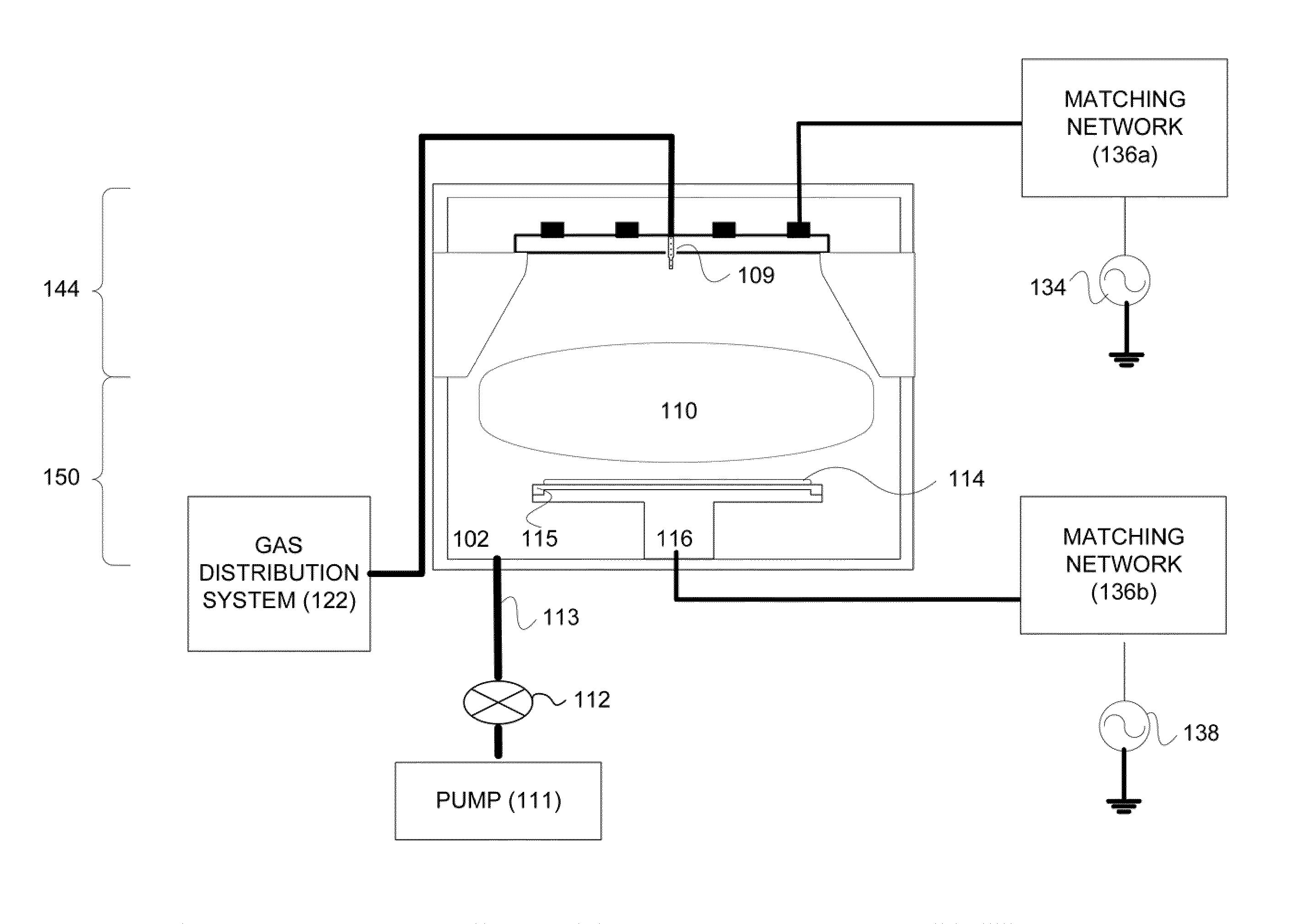
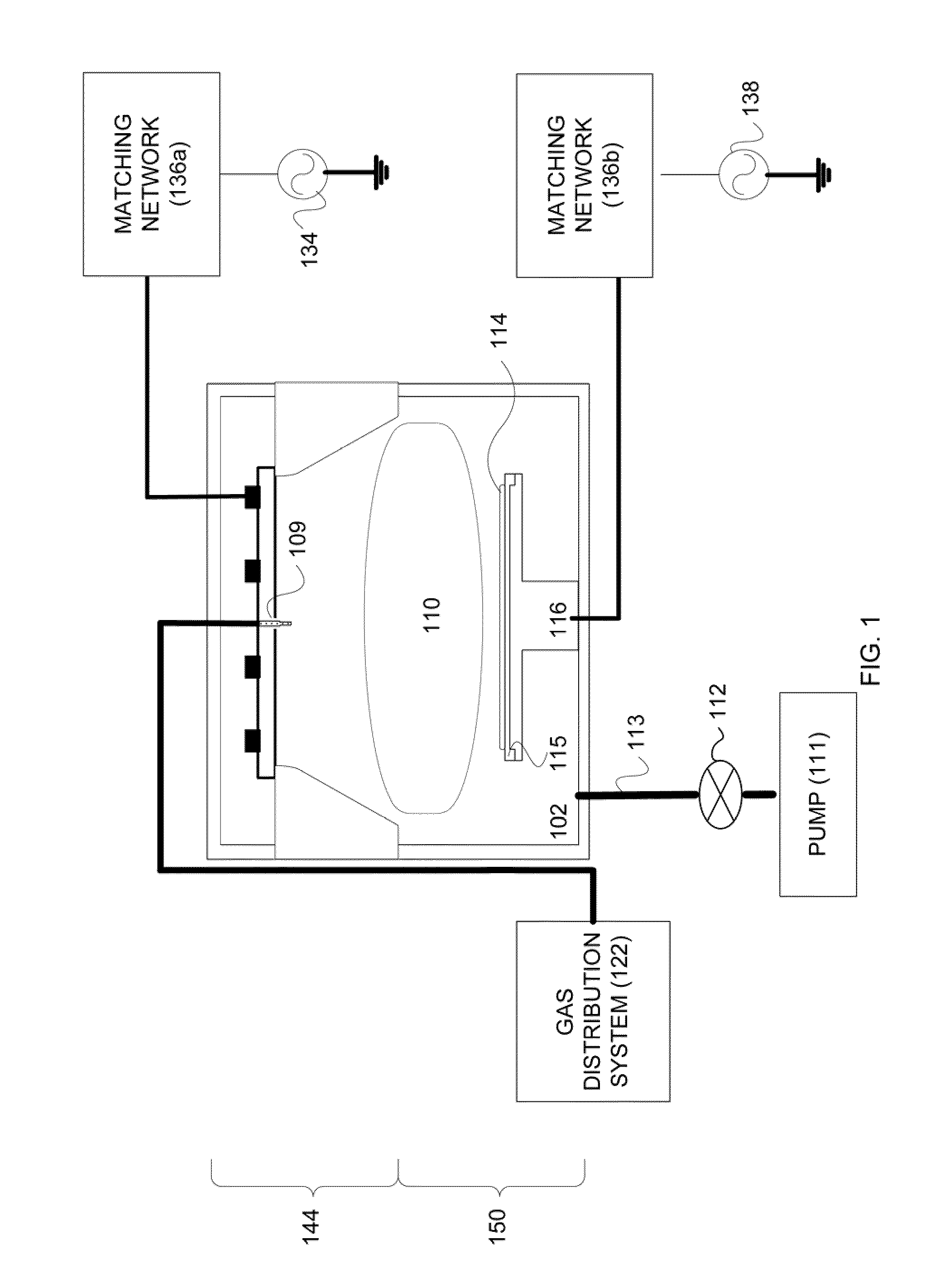
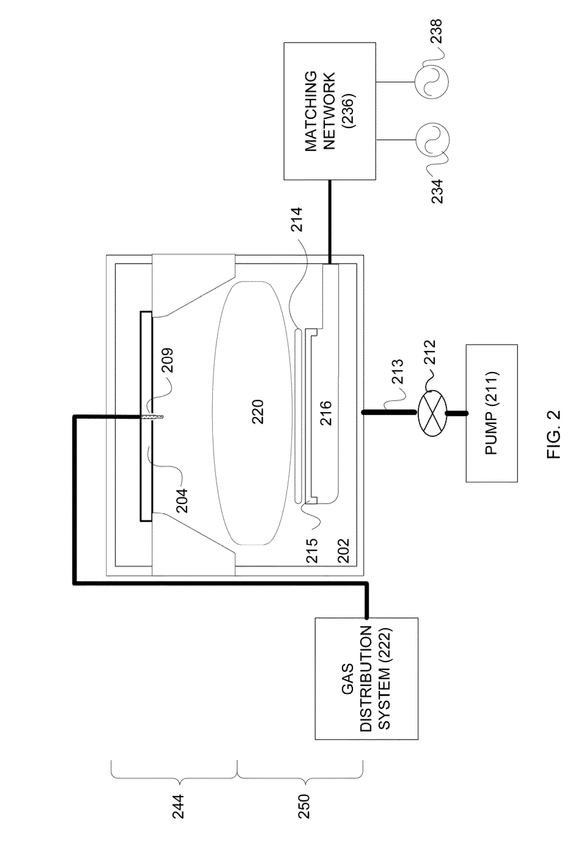
[0029]While not wishing to be bound by theory, it is believed by the inventor herein that a robot device can perform a set of service procedures on a plasma processing system. As previously described, in the normal course of operation, a plasma processing system may need to be serviced with a set of pre-defined service procedures. For example, the plasma chamber may need to be cleaned, or ...


PUM

PropertyMeasurementUnit
frictionaaaaaaaaaa
weightaaaaaaaaaa
torqueaaaaaaaaaa

Abstract

A method for servicing a plasma processing system. The plasma processing system may include a plasma chamber. The plasma chamber may include a top piece and a bottom piece, wherein the top piece may be disposed above the bottom piece. The method may include using a robot device to control a lift mechanism to lift the top piece from the bottom piece. The method may also include extending a first member of the robot device into the top piece to perform a first set of tasks according to a first set of service procedures. The method may also include extending a second member of the robot device into the bottom piece to perform a second set of tasks according to a second set of service procedures.

Description

CROSS-REFERENCE TO RELATED APPLICATIONS / PRIORITY CLAIM[0001]This application is a divisional application of and claims the benefit under 35 U.S.C. 120 of U.S. patent application Ser. No. 11 / 092,848 (“APPARATUS FOR SERVICING A PLASMA PROCESSING SYSTEM WITH A ROBOT”) filed on Mar. 28, 2005 by Andrew D. Bailey III.BACKGROUND OF THE INVENTION[0002]The present invention relates in general to substrate manufacturing technologies and in particular to an apparatus for servicing a plasma processing system with a robot.[0003]In the processing of a substrate, e.g., a semiconductor wafer or a glass panel such as one used in flat panel display manufacturing, plasma is often employed. As part of the processing of a substrate (chemical vapor deposition, plasma enhanced chemical vapor deposition, physical vapor deposition, etc.) for example, the substrate is divided into a plurality of dies, or rectangular areas, each of which will become an integrated circuit. The substrate is then processed in a ...

Claims


Application Information

Patent Timeline
Patent Type & Authority Applications(United States)
IPC IPC(8): B23P6/00B23P19/04
CPCB08B1/00B08B9/00B25J5/00Y10T29/49723H01J37/32862H01L21/67751H01J37/32743B08B1/10B08B1/143B25J18/00
Inventor BAILEY, III, ANDREW D.
Owner LAM RES CORP
Learn More