
Method for producing high-resistance simox wafer

a technology of high-resistance simox and simox, which is applied in the direction of semiconductor/solid-state device manufacturing, basic electric elements, electric apparatus, etc., can solve the problem of particularly reducing the resistance of high-resistance wafers from the desired value, and achieve the effect of suppressing the occurrence of thermal donors

Inactive Publication Date: 2010-01-28
SUMCO CORP
View PDF14 Cites 5 Cited by
  • Summary
  • Abstract
  • Description
  • Claims
  • Application Information

AI Technical Summary

Benefits of technology

[0017]Moreover, the thermal donor means that oxygen and vacancies are changed into donors by the heat treatment at about 450° C., and if the thermal donor is generated, the resistivity particularly lowers from a desired value in a high-resistance wafer.
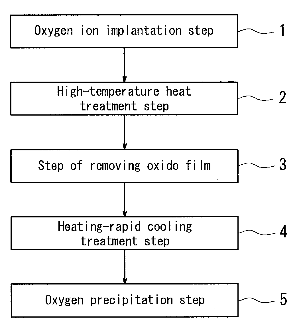
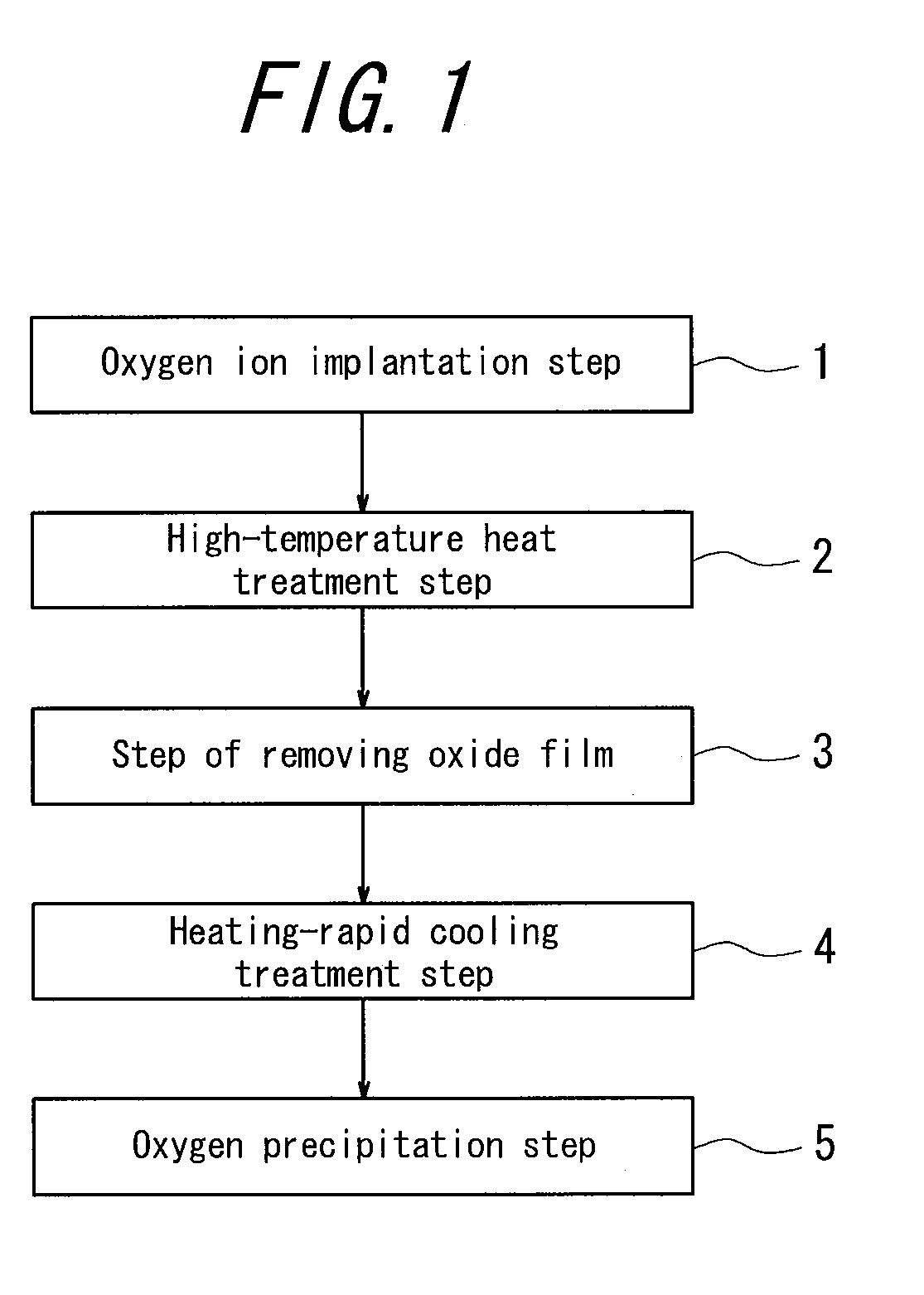
[0018]In order to achieve the above object, the inventors have made various studies about a method for reducing oxygen diffused toward the interior of the wafer due to the heat treatment at a high temperature in an oxidizing atmosphere. As a result, there has been reached a method wherein a heating-rapid cooling treatment (RTA (Rapid Thermal Annealing) treatment is a typical example) is conducted after the heat treatment at a high temperature in an oxidizing atmosphere to implant vacancies from a surface of a wafer into an interior thereof to thereby easily precipitate oxygen diffused inside of the wafer during the heat treatment.
[0026]According to the invention, it is possible to provide a high-resistance SIMOX wafer in which a high-resistance silicon wafer is used and subjected to a heat treatment at a high temperature in an oxidizing atmosphere and then a heating-rapid cooling treatment, whereby oxygen diffused inside of the wafer due to the heat treatment at the high temperature in the oxidizing atmosphere can be precipitated through vacancies implanted by the heating-rapid cooling treatment to reduce oxygen inside the wafer to thereby suppress the occurrence of thermal donor.

Problems solved by technology

Moreover, the thermal donor means that oxygen and vacancies are changed into donors by the heat treatment at about 450° C., and if the thermal donor is generated, the resistivity particularly lowers from a desired value in a high-resistance wafer.

Method used


Image

  • Method for producing high-resistance simox wafer
  • Method for producing high-resistance simox wafer

Examples


examples

[0041]A high-resistance SIMOX wafer prepared by the production method shown in FIG. 1 is subjected to a heat treatment at 450° C. for 1 hour, and then a resistivity thereof is measured by an SR (Spreading Resistance) method. The SR method is a method wherein the wafer is polished in an oblique direction and its resistivity value is measured in a depth direction.

[0042]In SIMOX wafers of Examples 1 to 6, a high-resistance silicon wafer shown in Table 1 is subjected to an RTA treatment under conditions shown in Table 1 after the oxygen ion implantation and high-temperature heat treatment steps.

[0043]On the other hand, the RTA treatment is not conducted in SIMOX wafer of Comparative Example 1. The measuring conditions and results are shown in Table 1.

TABLE 1RTA treatmentResistivityHighestof silicontemperatureCooling rateMeasured valuewafer [Ωcm][° C.][° C. / sec](resistivity)Example 1100110033100Example 2100120033100Example 3100135033100Example 410010003370Example 510012001070Example 6701...


PUM

PropertyMeasurementUnit
resistivityaaaaaaaaaa
temperatureaaaaaaaaaa

Abstract

A method for producing a high-resistance SIMOX wafer wherein oxygen diffused inside of a wafer by the heat treatment at a high temperature in an oxidizing atmosphere can be reduced to suppress the occurrence of thermal donor. In one embodiment, a heating-rapid cooling treatment is conducted after the heat treatment at a high temperature in an oxidizing atmosphere to implant vacancies from a surface of a wafer into an interior thereof to thereby easily precipitate oxygen diffused inside the wafer during the heat treatment.

Description

BACKGROUND OF THE INVENTION[0001]1. Field of the Invention[0002]This invention relates to a method for producing an SIMOX (Separation by Implanted Oxygen) wafer, and more particularly to a method for producing a high-resistance SIMOX wafer wherein oxygen diffused inside of the wafer by a heat treatment at a high temperature in an oxidizing atmosphere for forming an SOI (Silicon on Insulator) layer is reduced to suppress an occurrence of thermal donor.[0003]2. Description of the Related Art[0004]As one of production methods for SOI wafer, there is a SIMOX method (see Non-patent Document 1). Although there are some processes in the SIMOX method, the current SIMOX technique is based on a low-dose SIMOX technique (see Non-patent Document 2).[0005]In the low-dose SIMOX wafer, since a thickness of BOX (Buried Oxide) layer is thin, the reliability of BOX comes into problem. In order to improve it, there have been developed ITOX (Internal Thermal Oxidation) technique (see Non-patent Documen...

Claims


Application Information

Patent Timeline
Patent Type & Authority Applications(United States)
IPC IPC(8): H01L21/762
CPCH01L21/76243
Inventor AOKI, YOSHIROADACHI, NAOSHI
Owner SUMCO CORP
Learn More