
Intra-cavity non-degenerate laguerre mode generator

a generator and cavity technology, applied in the field of lasers, can solve the problems of -power lasers, exacerbated problems, and limited beam quality

Active Publication Date: 2010-01-28
OL SECURITY LIABILITY CO
View PDF10 Cites 8 Cited by
  • Summary
  • Abstract
  • Description
  • Claims
  • Application Information

AI Technical Summary

Benefits of technology

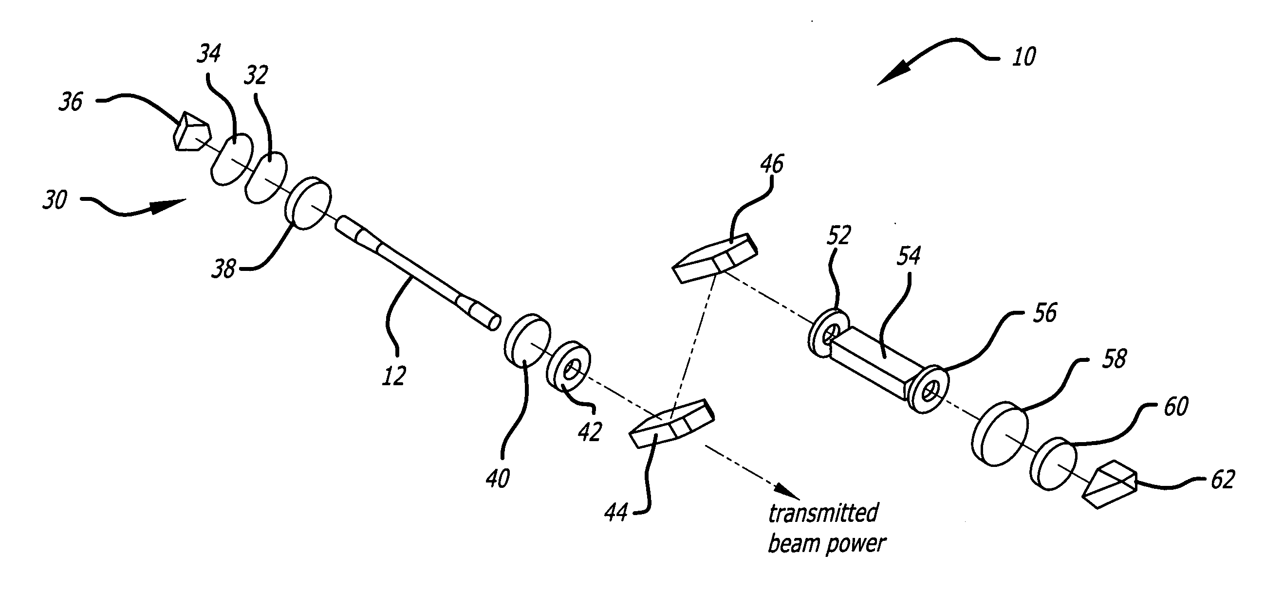
The present invention provides a lasing method that uses a high-power solid-state laser resonator. The method includes compensating for radial birefringence in the resonator to induce it to operate in a high-order non-degenerate Laguerre-Gaussian mode and utilizing polarized outcoupling of lasing energy at that mode. The method also includes changing an outcoupling preference, which can include changing an outcoupling polarization or the orientation of a prism in the resonator. The method helps to prevent lower order Laguerre modes from appearing in the output of the resonator and ensures a longer gain lifetime of the resonator.

Problems solved by technology

In addition, beam quality is typically limited in high-power lasers due to thermal distortion of optical elements, primarily by heat loading of the gain medium.
This problem is exacerbated at high power levels.
While some have approached this problem with larger aperture sizes, with this approach the beam quality and efficiency are typically affected adversely.
However, this generally limits the power of the resulting beam.
That is, with an improved output aperture area fill, higher power is not possible without damaging the associated optical system.
Consequently, designers of high power lasers have been forced to compromise between beam size or power and beam quality and vice versa.

Method used


Image

  • Intra-cavity non-degenerate laguerre mode generator
  • Intra-cavity non-degenerate laguerre mode generator
  • Intra-cavity non-degenerate laguerre mode generator

Examples


Embodiment Construction

[0024]Illustrative embodiments and exemplary applications will now be described with reference to the accompanying drawings to disclose the advantageous teachings of the present invention.

[0025]While the present invention is described herein with reference to illustrative embodiments for particular applications, it should be understood that the invention is not limited thereto. Those having ordinary skill in the art and access to the teachings provided herein will recognize additional modifications, applications, and embodiments within the scope thereof and additional fields in which the present invention would be of significant utility.

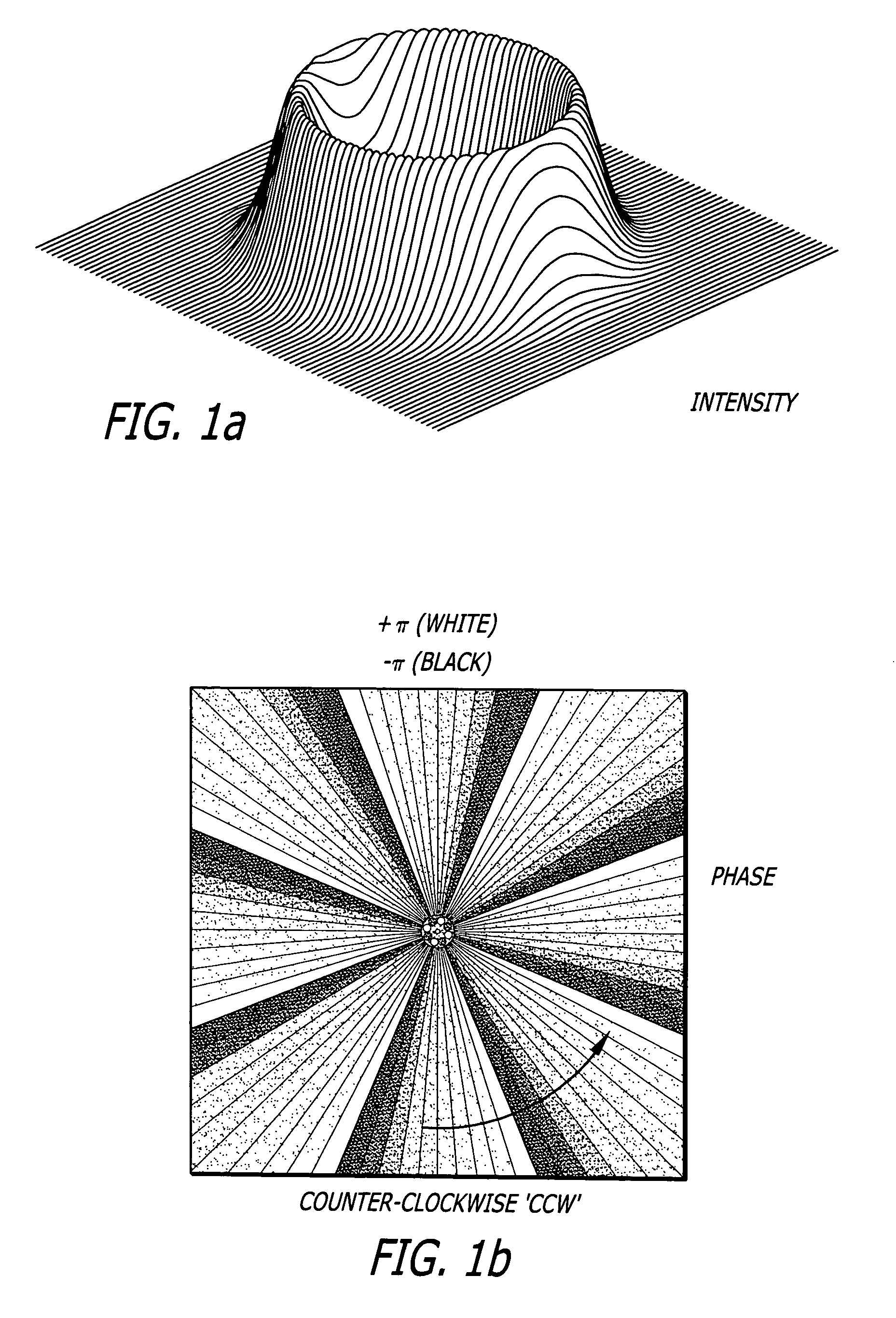
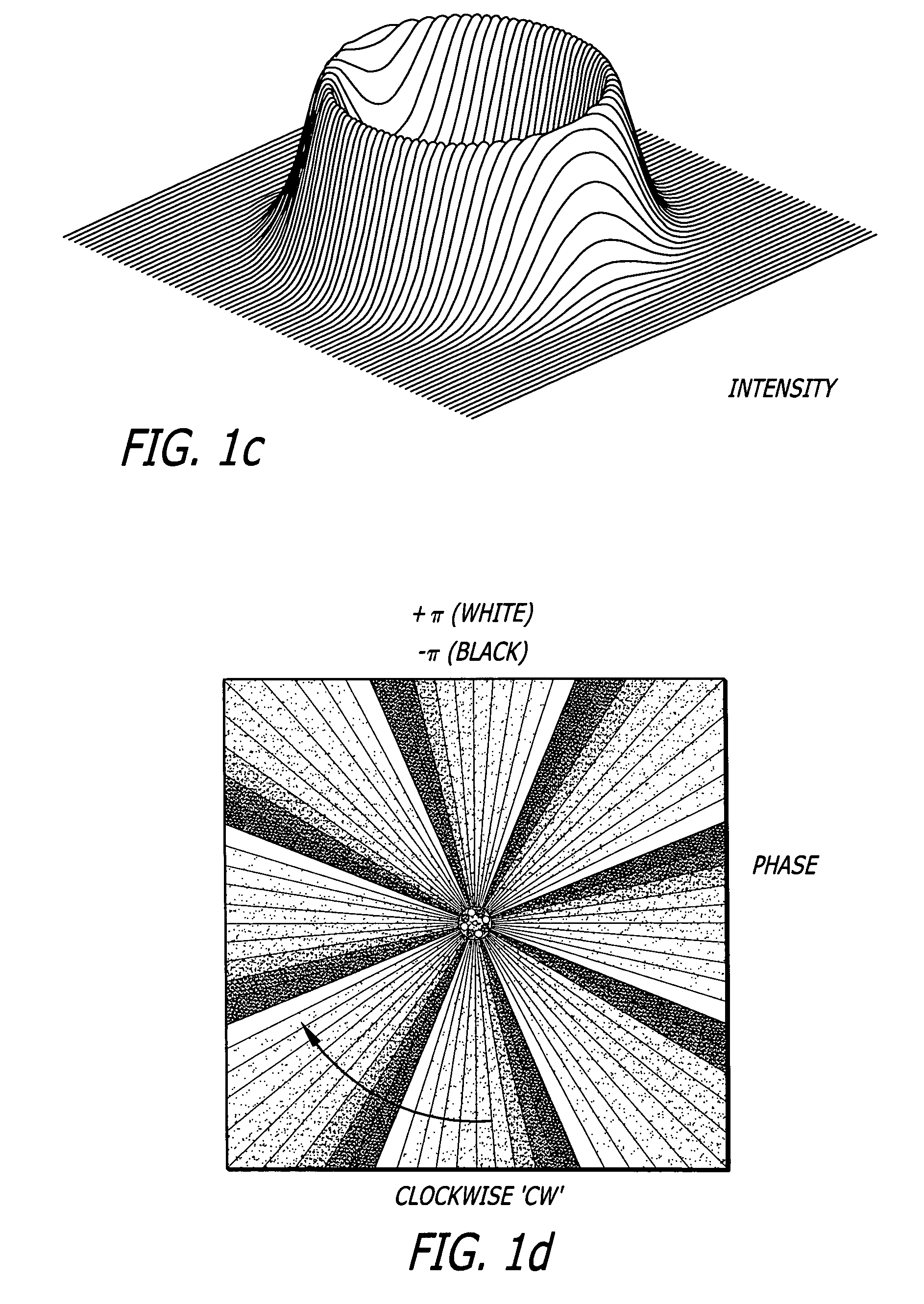
[0026]In accordance with the present teachings, non-degenerate Laguerre-Gaussian ring modes are created in a laser resonator, especially in a high-power, solid-state laser resonator. Laguerre-Gaussian modes are characterized by a spiral phase front, exp(imθ), and possess angular momentum. The phase rotates from zero to 2πm where ‘m’ is an integer tha...


PUM


Abstract

A lasing method including the steps of providing a laser resonator; utilizing birefringence compensation in said resonator whereby said resonator is induced to operate in a Laguerre-Gaussian higher order mode; and utilizing polarized outcoupling of lasing energy at said higher order mode from said resonator. In the illustrative application, the laser resonator is a high-power, solid-state laser resonator. In the specific embodiment, the inventive method further includes the step of changing an outcoupling preference for a non-degenerate high-order Laguerre-Gaussian mode. In one embodiment, the step of changing outcoupling preference includes the step of changing an outcoupling polarization. In another embodiment, the step of changing outcoupling preference includes the step of changing an orientation of a roof edge of a prism in the laser resonator. Lower order Laguerre modes are discouraged from appearing in an output of the resonator by adding loss at the center of the rod aperture of the resonator or detuning the orientation of a first or a second quarter-wave plate. In the illustrative embodiment, the gain lifetime of the resonator is longer than an interpulse period thereof.

Description

[0001]This invention was made with Government support under Contract No. F29601-97-C-0001 awarded by the Department of the Army. Accordingly, the United States Government may have certain rights in this inventionBACKGROUND OF THE INVENTION[0002]1. Field of the Invention[0003]The present invention relates to lasers. More specifically, the present invention relates to high-energy or high average power lasers.[0004]2. Description of the Related Art[0005]High-power lasers (i.e. lasers operating at power levels in excess of 100 watts) are used in a variety of commercial, industrial and military applications. For these applications, there is an ongoing need for more power and more efficiency. In addition, beam quality is typically limited in high-power lasers due to thermal distortion of optical elements, primarily by heat loading of the gain medium. This problem is exacerbated at high power levels. While some have approached this problem with larger aperture sizes, with this approach the...

Claims


Application Information

Patent Timeline
Patent Type & Authority Applications(United States)
IPC IPC(8): H01S3/098H01S3/10
CPCH01S3/061H01S3/07H01S3/08045H01S3/08059H01S3/08072H01S2301/203H01S3/083H01S3/115H01S3/1618H01S3/1643H01S2301/20H01S3/0813
Inventor STULTZ, ROBERT D.MATTHEWS, STEVEN C.HENDRY, BILLIE G.
Owner OL SECURITY LIABILITY CO
Learn More