Vehicle lamp having prismatic element

Inactive Publication Date: 2005-09-27
FER FAHRZEUGELEKTRIK GMBH
View PDF18 Cites 159 Cited by
  • Summary
  • Abstract
  • Description
  • Claims
  • Application Information

AI Technical Summary

Benefits of technology

[0007]In comparison the object of the invention is to develop a vehicle lamp of the kind set forth in the opening part of this specification, in such a way that it can be produced in a substantially easier and less expensive manner.
[0010]In terms of the side flashing lamp referred to in the opening part of this specification, this means that a very simple structure permits light emission not only in the transverse direction of the vehicle but also forwardly and rearwardly in the direction of travel.
[0011]The plurality of prismatic elements which are associated with a plurality of light emitting diodes can be integrally connected together and thus form an intermediate light cover or panel which is arranged between a flat board which carries all the light emitting diodes and which permits particularly simple wiring for and power supply to the light emitting diodes and the light exit cover extending in substantially parallel relationship with that board.

Problems solved by technology

In that respect the problem arises that the light emitted by the light emitting diodes used as the light source is to be radiated into a spatial angle embracing nearly 180° from a cup-shaped housing whose substantially flat light exit opening is disposed in an also substantially flat surface of the vehicle body and facing in the transverse direction of the vehicle, and is covered over by a substantially flat light exit cover.
A similar problem can also arise in relation to other vehicle lamps which are not used as side flashing lamps.
A disadvantage with that known arrangement is the extremely complex structure of the boards which carry the individual light emitting diodes and which have to be mounted in individually supported relationship on a main board in order to implement the wiring of the light emitting diodes.

Method used


Image

  • Vehicle lamp having prismatic element
  • Vehicle lamp having prismatic element
  • Vehicle lamp having prismatic element

Examples


Embodiment Construction

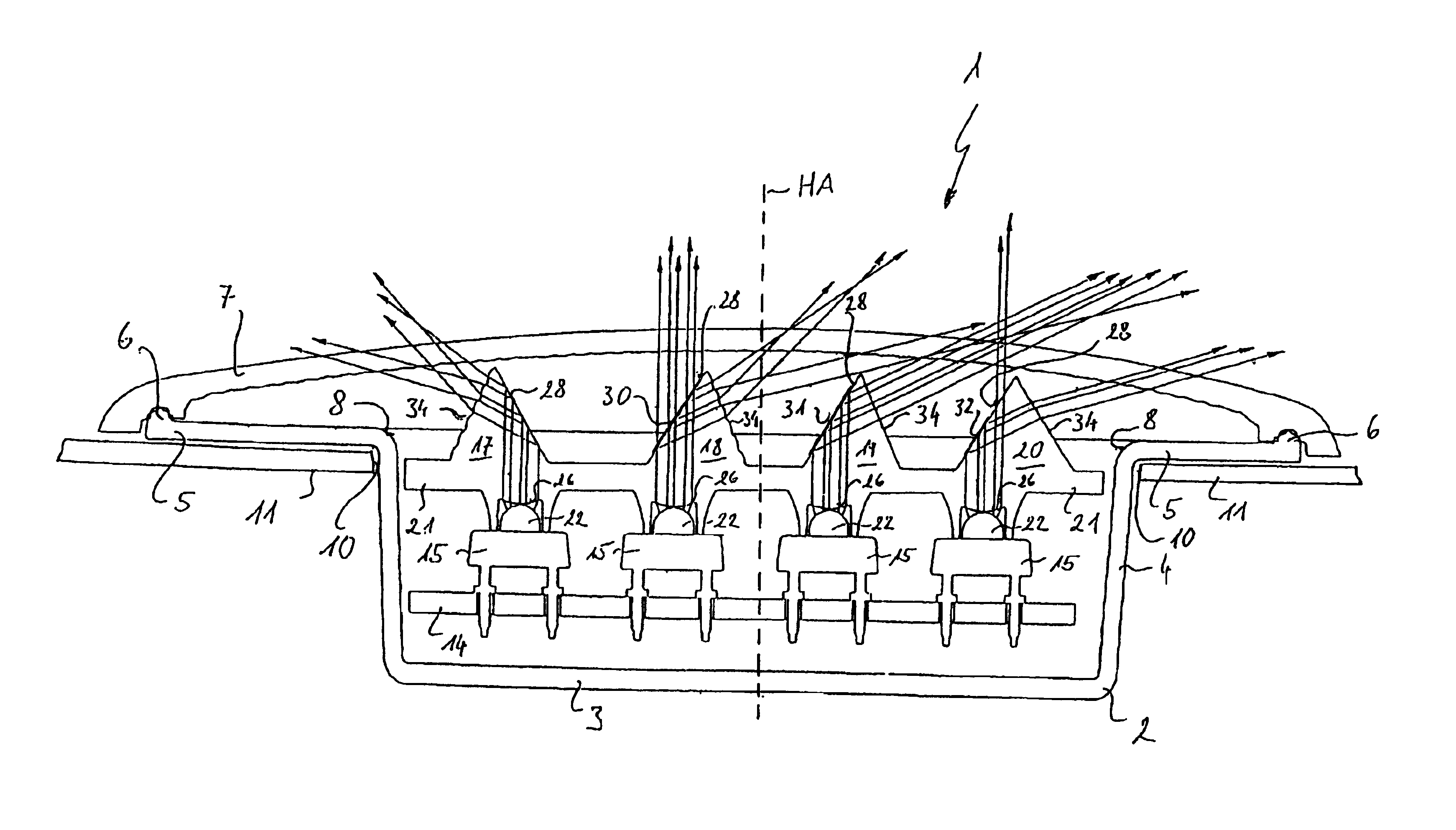
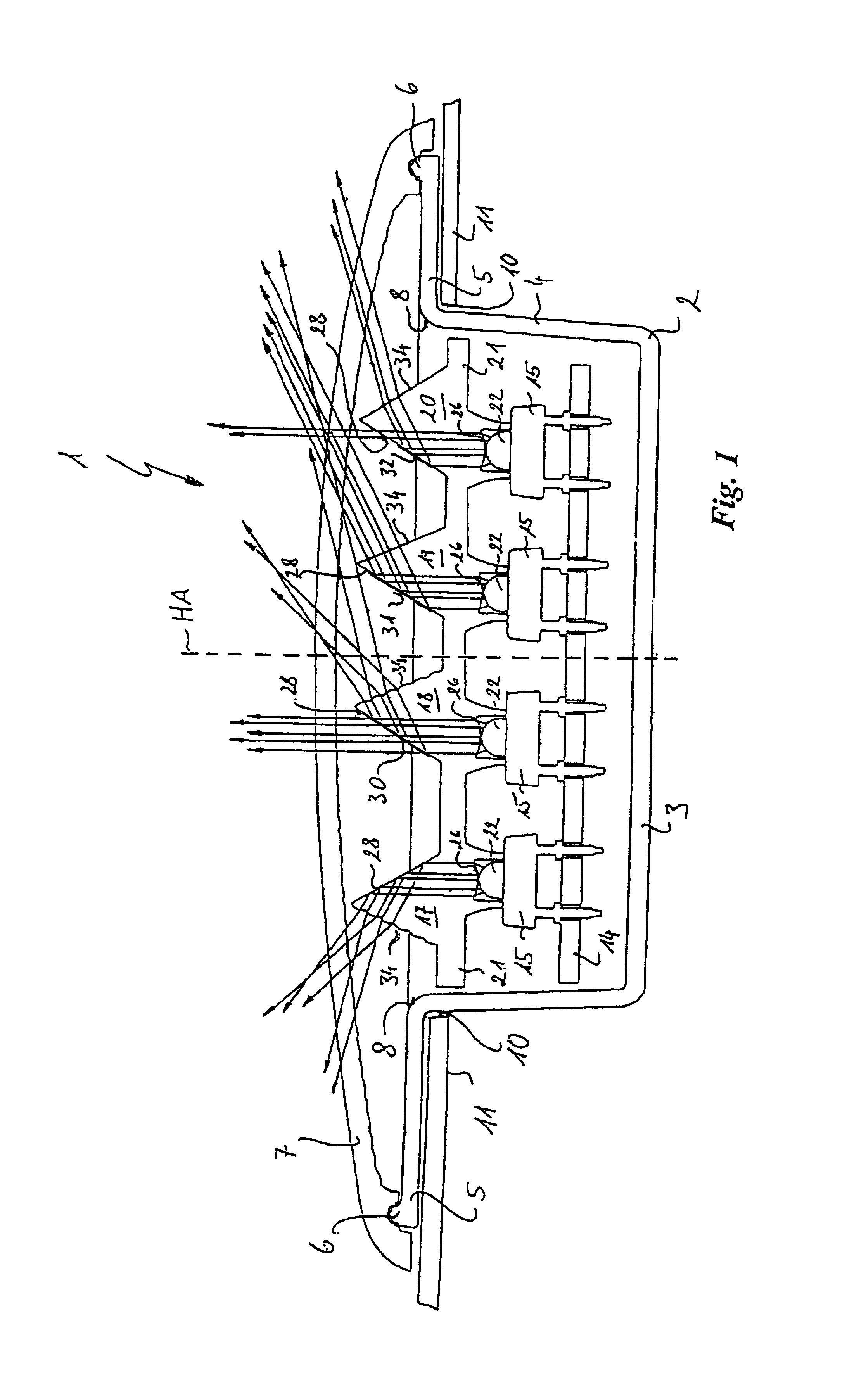
[0018]Referring to FIG. 1, diagrammatically shown therein is a vehicle lamp 1 according to the invention which has a cup-shaped housing 2 including a housing bottom 3, a housing wall 4 which extends substantially perpendicularly to the housing bottom 3 and encloses the periphery thereof, a mounting flange 5 which adjoins the upper edge of the housing wall 4 and extends in an annular configuration therearound, and a light exit cover 7 which is sealingly connected to the outer edge 6 of the mounting flange 5 and which closes the housing in an outward direction. The upper edge of the housing wall 4 defines a light exit opening 8 from which the light exit cover 7 is at a spacing, by virtue of its flat, dome-shaped curvature, in the direction of the main axis HA of the housing, which extends substantially perpendicularly both with respect to the housing bottom 3 and also with respect to the light exit cover 7.

[0019]The housing 2 is fitted from the exterior into an opening 10 in the vehic...


PUM


Abstract

A vehicle side-flashing lamp includes: a cup-shaped housing; a light exit opening opposite the housing bottom; and a light exit cover which covers the light exit opening. At least one light-emitting diode emits light outwardly at least partially at an angle which is large with respect to the main axis of the housing. A prismatic element, defined by first, second and third boundary surfaces, is arranged in front of the light-emitting diode in such a way that an emitted light beam passes through the first boundary surface into the prismatic element and is at least partially reflected at the second boundary surface, which is inclined with respect to the central axis of the light beam, in such a way that the reflected part issues from the prismatic element through the third boundary surface.

Description

BACKGROUND OF THE INVENTION[0001]The invention concerns a vehicle lamp, in particular a side flashing lamp for motor vehicles, as set forth in the classifying portion of claim 1.[0002]A vehicle lamp of that kind is known from German utility model No 297 20 060, which is to be used as a flashing lamp which is mounted laterally to a motor vehicle and in which, besides the emission of light in the transverse direction of the vehicle, there is also a need for light to be emitted in the longitudinal direction of the vehicle, in particular rearwardly but also forwardly.[0003]In that respect the problem arises that the light emitted by the light emitting diodes used as the light source is to be radiated into a spatial angle embracing nearly 180° from a cup-shaped housing whose substantially flat light exit opening is disposed in an also substantially flat surface of the vehicle body and facing in the transverse direction of the vehicle, and is covered over by a substantially flat light exi...

Claims


Application Information

Patent Timeline
IPC IPC(8): F21V5/00F21V7/00F21S8/10
CPCF21S48/215F21S48/2212F21S48/236F21V7/0091F21W2101/12F21Y2101/02F21Y2115/10F21S43/14F21S43/26F21S43/241F21S43/247F21S43/315F21W2103/20
Inventor KUNSTLER, ROLF
Owner FER FAHRZEUGELEKTRIK GMBH
Why Eureka
Try Eureka