Inter-blade sealing for a turbine or compressor wheel of a turbine engine

Active Publication Date: 2016-08-09
SN DETUDE & DE CONSTR DE MOTEURS DAVIATION S N E C M A
View PDF10 Cites 0 Cited by
  • Summary
  • Abstract
  • Description
  • Claims
  • Application Information

AI Technical Summary

Benefits of technology

The invention provides a simple, effective, and inexpensive solution to the problem of friction wear in inserts used in machining processes. The insert has a single bearing surface that is subjected to uniform wear, and it is more stable than previous designs. The insert has cooling grooves for accurately cooling the edges of the platforms and wear indicators that help determine when the insert needs replacement. The wear indicators are formed by annular scores in the outer cylindrical surface of the insert.

Problems solved by technology

Furthermore, the insert allows the blades to be removed individually, which is not true when using the boxes of the prior art.

Method used


Image

  • Inter-blade sealing for a turbine or compressor wheel of a turbine engine
  • Inter-blade sealing for a turbine or compressor wheel of a turbine engine
  • Inter-blade sealing for a turbine or compressor wheel of a turbine engine

Examples


Embodiment Construction

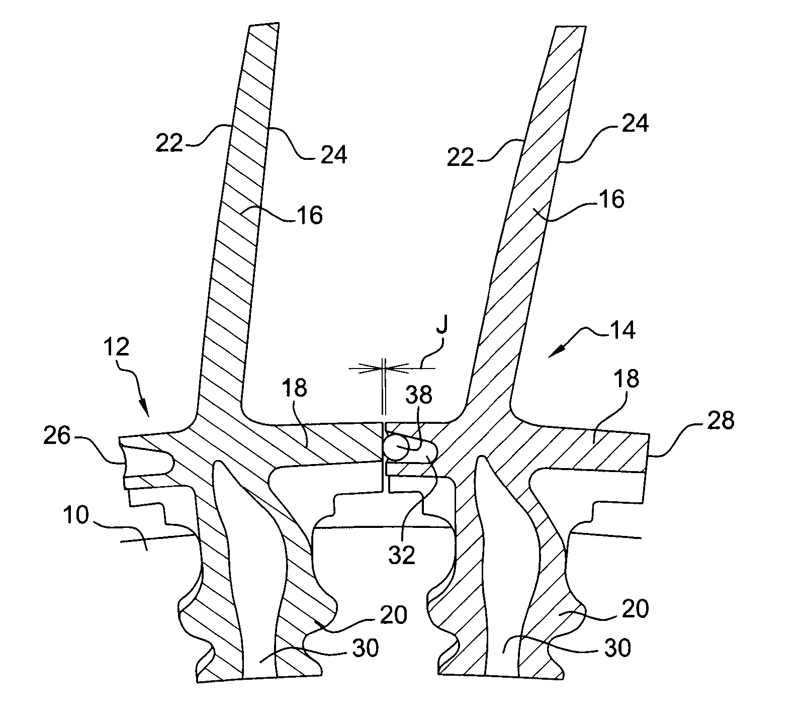
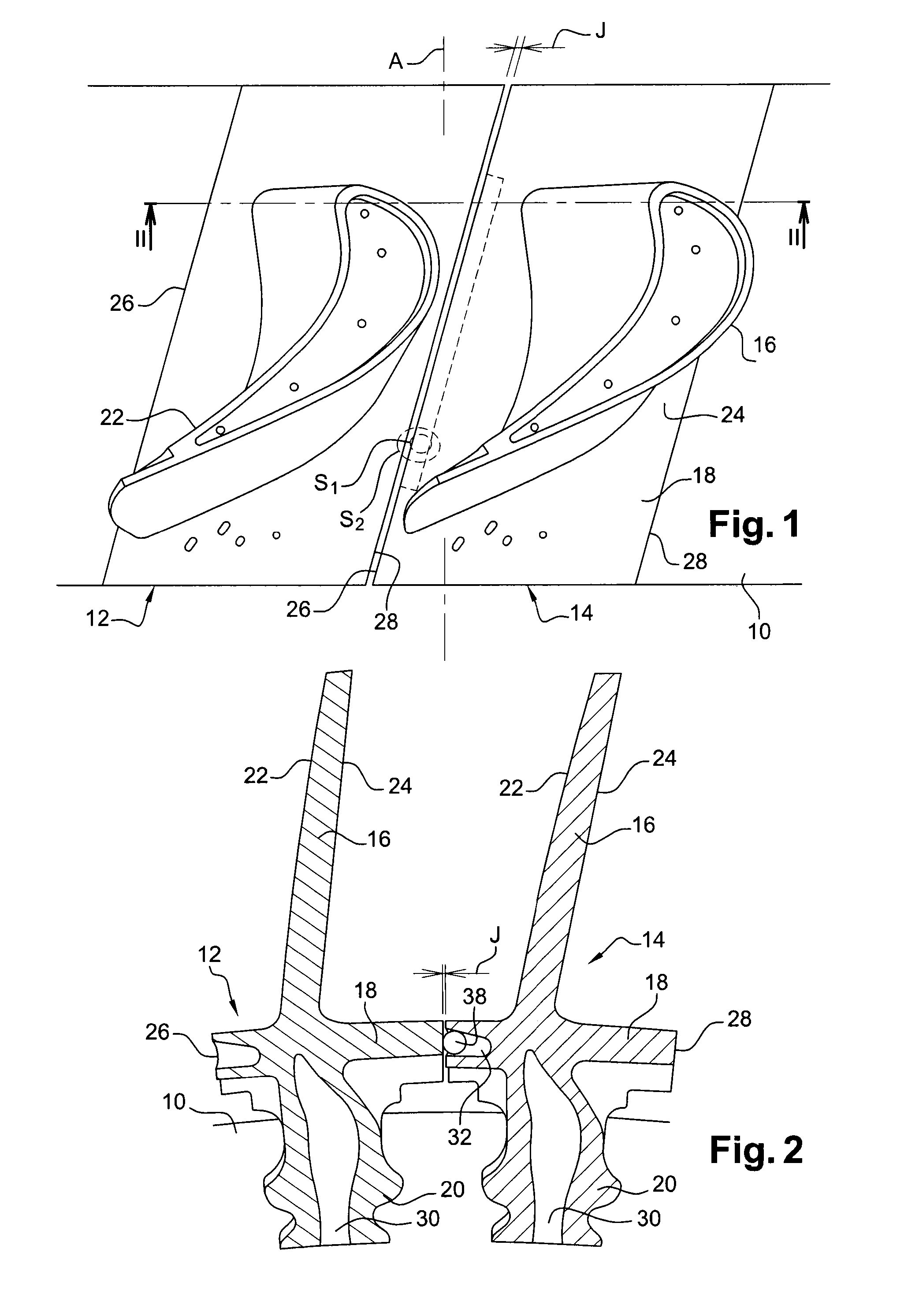
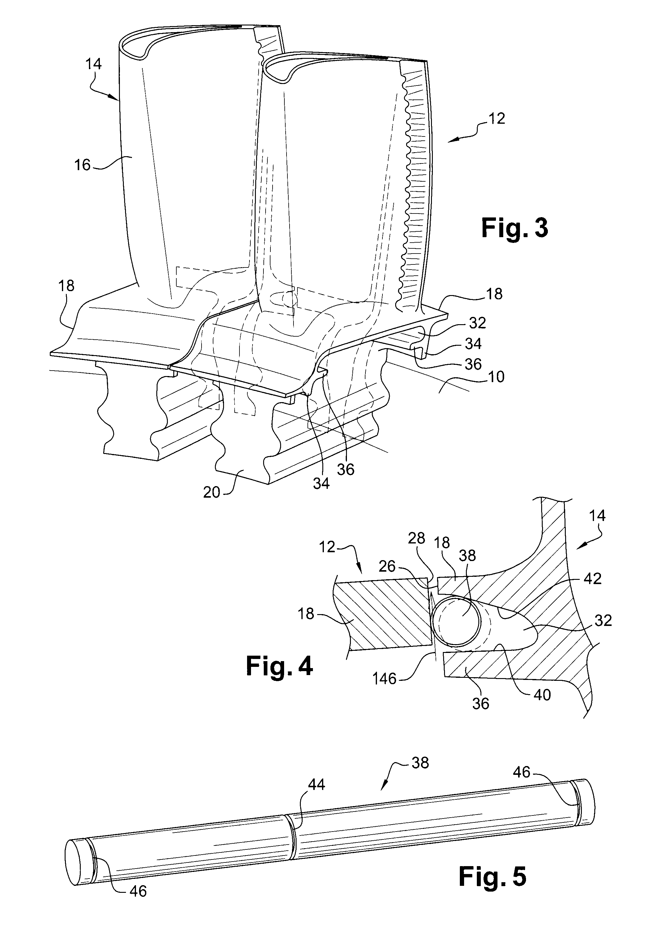
[0030]Reference is made initially to FIGS. 1 to 3, which are highly diagrammatic and fragmentary views of a compressor or turbine wheel of a turbine engine such as an airplane turboprop or turbojet, the wheel comprising a disk 10 having blades 12, 14 at its periphery, with only two of them being shown in the drawings.

[0031]Each blade 12, 14 comprises an airfoil 16 connected by a platform 18 to a root 20 that presents a section of Christmas-tree shape in the example shown. The root 20 of each blade is engaged in a slot (not shown) of complementary shape in the periphery of the disk 10.

[0032]The airfoil 16 of each blade has a pressure side 22 and a suction side 24 that are connected together at an upstream end by a leading edge and at a downstream end by a trailing edge, where “leading” and “trailing” are relative to the flow of gas through the compressor or the turbine.

[0033]The platform 18 of each blade is generally in the form of a parallelepiped having two straight side edges 26 a...


PUM


Abstract

An inter-blade sealing for a turbine or compressor wheel of a turbine engine includes inserts engaged in longitudinal cavities in side edges of platforms of blades and bearing, in operation, against facing side edges of platforms of adjacent blades. Each insert has a cylindrical elongate shape and includes in its outer cylindrical surface at least one annular groove for passing platform cooling air.

Description

BACKGROUND OF THE INVENTION[0001]1. Field of the Invention[0002]The present invention relates to a compressor or turbine wheel for a turbine engine such as an airplane turboprop or turbojet, the wheel including inter-blade sealing means.[0003]2. Description of the Related Art[0004]A compressor or turbine wheel of a turbine engine comprises a disk that includes slots in its periphery for engaging blade roots, these roots being connected to the airfoils of the blades via platforms that are generally of parallelepiped shape and that, when in the mounted position on the disk, are spaced apart from one another by small amounts of clearance in the circumferential direction.[0005]A fraction of the flow of air for ventilating the blades penetrates into the spaces situated between the roots of the blades and it needs to be prevented from passing through the above-mentioned clearance between the platforms of the blades radially from the inside towards the outside by means of inter-blade seali...

Claims


Application Information

Patent Timeline
IPC IPC(8): F01D11/00F01D5/12F01D5/24
CPCF01D11/006F01D5/24F01D5/12Y02T50/672F05D2250/231F01D5/22Y02T50/60
Inventor ALQUIER, DAMIENBOURY, JACQUES AUGUSTE AMEDEECOURTIN, PASCALTRAN, HUU-THANH
Owner SN DETUDE & DE CONSTR DE MOTEURS DAVIATION S N E C M A
Why Eureka
Try Eureka