
Reflective polarization valve engine and projection display using the same

a technology of reflective polarization valve and projection display, which is applied in the direction of projection device, polarising element, picture reproducer, etc., can solve the problems of low heat resistance, pbs has limitation in beam incident angle, and the pbs has a limited range of beam incident angle, etc., and achieves low image performance and high cost.

Inactive Publication Date: 2005-02-03
DELTA ELECTRONICS INC
View PDF6 Cites 161 Cited by
  • Summary
  • Abstract
  • Description
  • Claims
  • Application Information

AI Technical Summary

Benefits of technology

[0009] In view of the foregoing, the invention wants to solve the problems of low image performance and high cost when using the PBS, prisms of unique shapes and peculiar optical elements.
[0013] B. By means of dichroic mirror, the light path is capable of change direction. Meanwhile, the entire light paths are highly concentrated and have more selectivity of arrangement, so as to achieve a projection system of smaller volume.
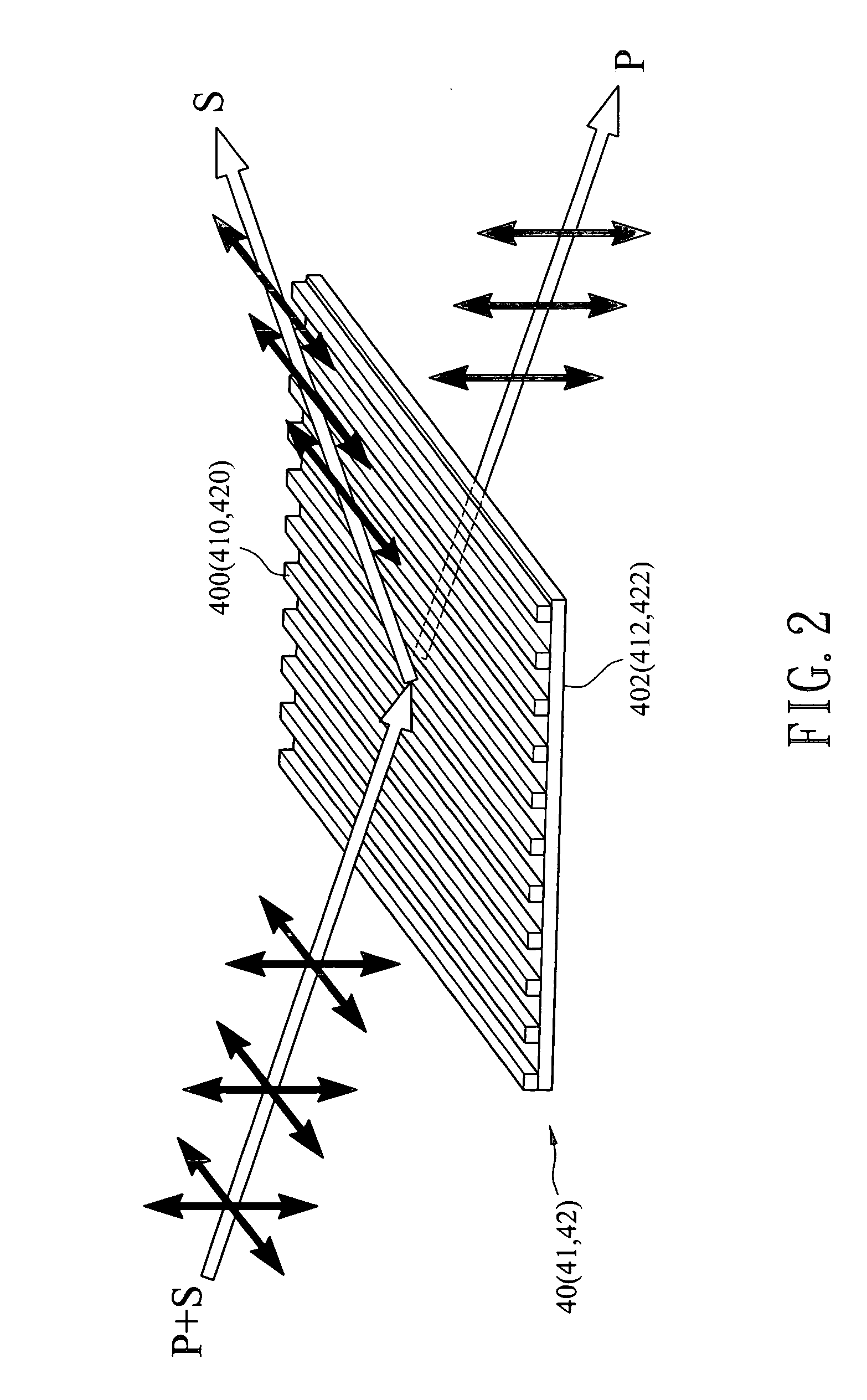
[0014] C. The wire-grid polarizer is produced via a semi-conductor producing procedures to provide an easier manufacturing process and lower costs.
[0015] D. Instead of drawbacks of color gradients, the invention achieves better color uniformity.
[0016] E. Specific arrangement of light paths provides better image performance.

Problems solved by technology

However, the application of a PBS causes some defects.
First, the PBS has low heat-resistance so that birefringence effect and decreasing of contrast luminance are formed due to heat-expansion of the PBS.
Second, the PBS has limitation in incident angles of beams.
Therefore, the light path becomes longer and causes energy loss.
In addition, the PBS reduces the purity of polarized beams because of its unstability, which makes an unsatisfactory performance of image combination.
However, they are expensive and have low heat-resistance.
Comparatively, because these optical elements' unique shapes are hard to manufacture and have a lack of general uses, they are difficult for mass production and thereby have higher costs.

Method used


Image

  • Reflective polarization valve engine and projection display using the same
  • Reflective polarization valve engine and projection display using the same
  • Reflective polarization valve engine and projection display using the same

Examples


Embodiment Construction

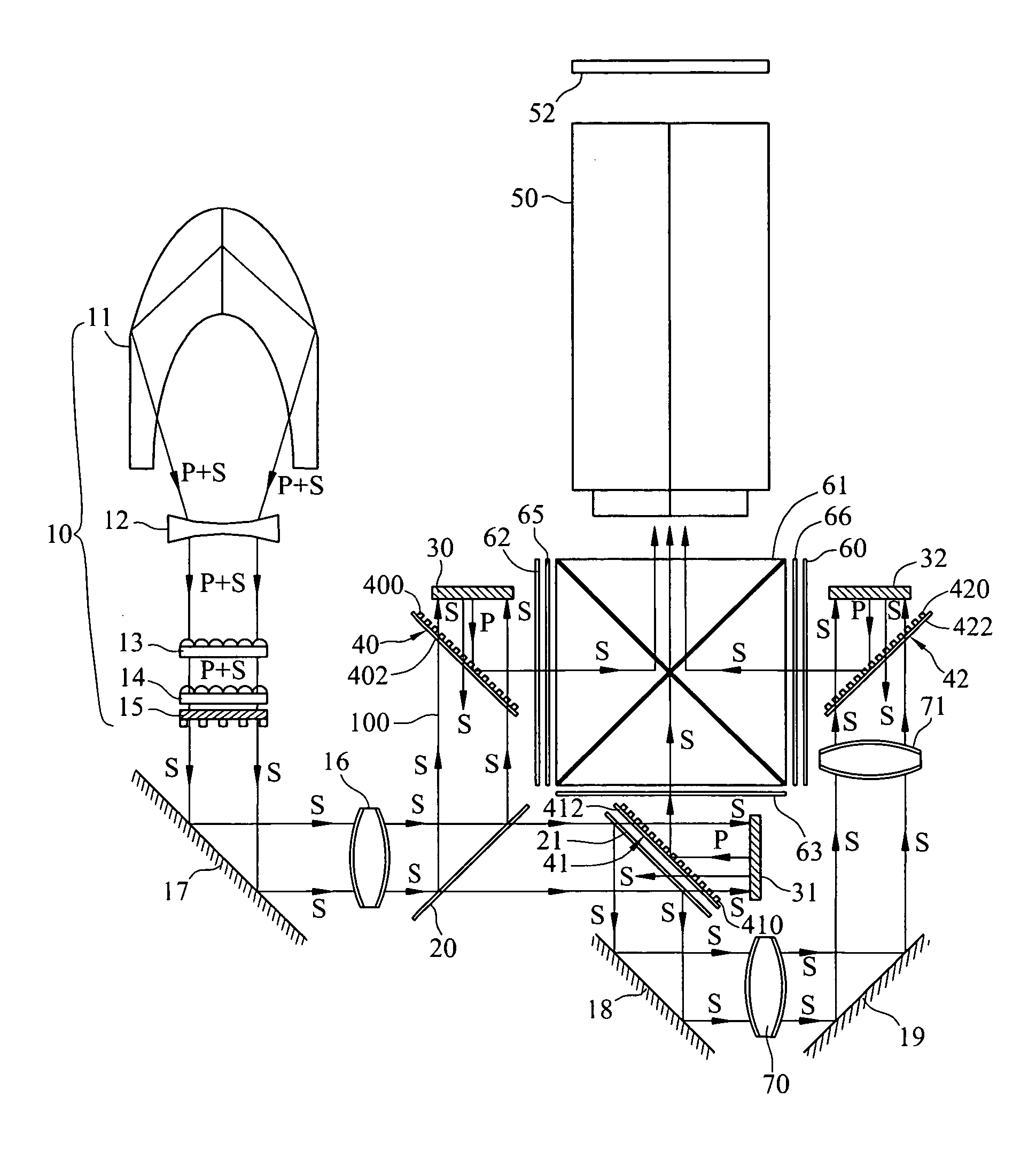
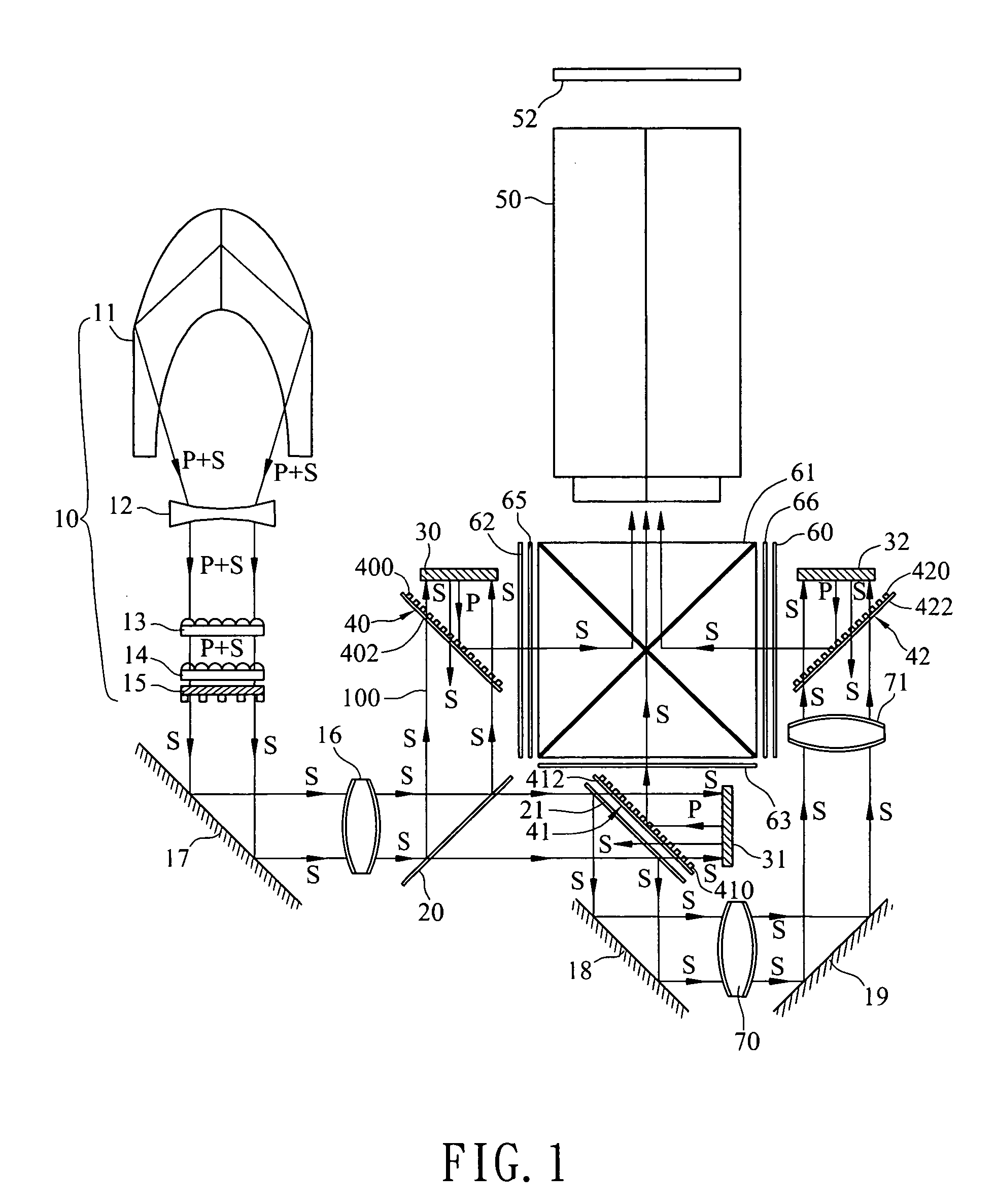
[0021] Please refer to FIG. 1, which shows a structural diagram of a projection display provided by a preferred embodiment according to the invention. The projection display comprises light source 10, dichroic mirror 20 and 21, reflective polarization valve 30, 31 and 32, wire-grid polarizer 40, 41 and 42, color-recombining unit 61 and projecting unit 50. The characteristic of the elements, their relations and the arrangement of light paths are illustrated in the following description.

[0022] Light source 10 provides a polarized white beam. It is a telecentric optical system, which includes a white lamp 11, a divergent lens 12, a lens array 13, 14 and a P / S converter 15. The white lamp 11 is an elliptical lamp of high efficiency. The white beam generated by the white lamp 11 first passes through the divergent lens 12 and then the lens array 13, 14. Next, the white beam goes through the S-polarized transformation via the P / S converter 15. After being splitted, the beams focus on the ...


PUM


Abstract

Reflective polarization valve engine and projection display are disclosed. Instead of prism PBS, the projector applies wire-grid polarizers with advantages of higher heat-resistance, no limitation of the incident angle and no birefringence effects, to provide excellent contrast luminance. The light source in the projector utilizes an elliptical lamp under a telecentric optical system to achieve higher efficiency and avoid color gradient. In addition, the light paths are in special arrangement. The original beam is first splitted into RGB, and then proceeding with color-recombining right after being polarized via wire-grid polarizers and analyzed by reflective polarization valves. Hence, the analyzed beams finally are recombined images with superior performances.

Description

BACKGROUND OF THE INVENTION [0001] 1. Field of Invention [0002] The present invention relates to a projection display and its optical engine with reflective polarization valves, and more particularly, to a projection device that utilizes a wire-grid polarizer, a telecentric optical system and specific arrangement of light path, which have the beams proceeding with color-recombining right after being analyzed by reflective polarization valves. [0003] 2. Related Art [0004] In the prior art, a LCOS (Liquid Crystal on Silicon) projector that uses LCOS as reflective polarization valve, is similar to LCD projector in portions of light-guiding, light-splitting and color-combining. The only difference is that the LCOS projector further applies prism PBS (Polarization Beam Splitter). PBS is a binding prism of two 45° isosceles right angle prisms. PBS reflects the S-polarized light of an incident beam and allows the P-polarized light to pass through. In general, the original beam emitting fro...

Claims


Application Information

Patent Timeline
IPC IPC(8): G02B5/30G02B27/18G03B21/14H04N9/31
CPCG02B5/3058G03B21/14H04N9/3197H04N9/315H04N9/3105G03B21/2073
Inventor LIAN, JAN-TIANHUANG, JUNE-JEI
Owner DELTA ELECTRONICS INC
Learn More