
Battery monitoring device

Inactive Publication Date: 2010-01-28
SON HONG K
View PDF16 Cites 43 Cited by
  • Summary
  • Abstract
  • Description
  • Claims
  • Application Information

AI Technical Summary

Problems solved by technology

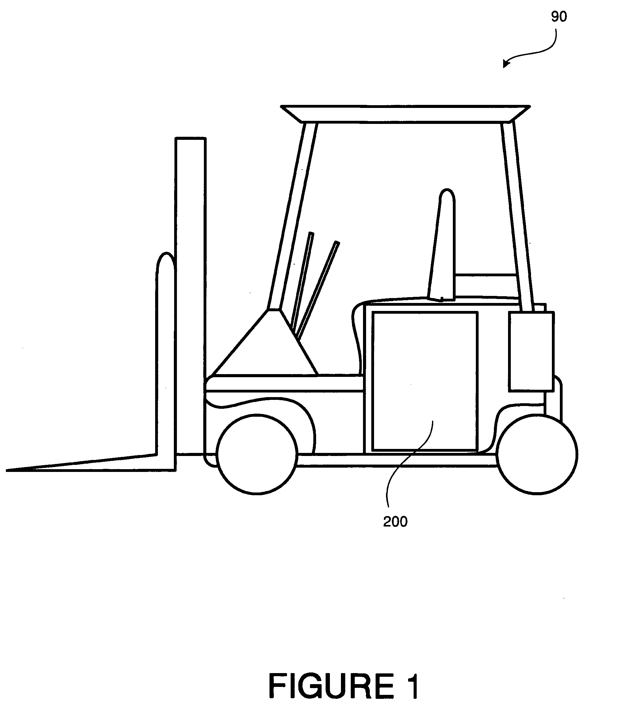
In addition, the chemistry of lead acid batteries is relatively uncomplicated, to the extent that the majority of automobile batteries found in cars and trucks worldwide, as well as the batteries that power industrial equipment such as forklifts, are based on plates of common metallic lead immersed in an electrolyte of water and sulfuric acid (see, for example, FIG. 1).
However, certain factors and effects of lead acid batteries can reduce their useful lifetime, and therefore necessitate costly replacement or reconditioning.
The effects of sulfation clog battery grids, impede recharging and can even expand and crack battery cell plates as the crystalline lead sulfate accumulates, destroying the battery.
Thus, not all of the lead consumed during discharge is returned to the battery plates during recharge, and the amount of usable active material necessary for generating electricity declines over time.
Sulfation also adversely affects the charging cycle, resulting in longer charging times, less efficient and incomplete charging, excessive heat generation (higher battery temperatures).
Increased battery temperatures can cause longer cool-down times and accelerate corrosion.
Sulfation is particularly harmful when batteries are stored or not operated for period of time, while in a state of depleted charge, in part because recrystallization occurs in the absence of the usual cycles of breakdown and regeneration of amorphous lead sulfate that occur during normal operation and recharging activities.
However, KONDO et al. relates only to a method for recycling lead acid batteries, and does not address extending the useful life or enhancing the performance of existing batteries.
Moreover, there are additional factors that can adversely impact useful battery life and performance.
In addition to sulfation, reduced lead acid battery life can also occur because of sub-optimal or insufficient levels of electrolyte being present in the battery, inter alia.
In particular, many varieties of lead acid batteries experience gradual loss of electrolyte fluid as a normal part of the battery's use cycle, which can be caused by evaporation due to heat generated as a by-product during discharge or recharging.
However, the process of checking water or electrolyte levels typically requires the operator to perform an inconvenient series of steps in order to access the batteries (for example, having to first open a battery compartment of a vehicle, then unscrew a valve cap on each cell in a battery pack in order to check fluid levels, and finally to replace the valve caps and close the battery compartment).
Moreover, the rate of fluid loss can vary depending on how often or how long the battery-powered equipment is operated, as well as ambient or internal battery temperature, inter alia, which can reduce the usefulness of a battery inspection schedule based on regular intervals.
As a result, battery electrolyte levels frequently go unchecked despite possible adverse effects on the batteries, leading to substantially increased operation or replacement costs for batteries that wear out early due to having been operated with insufficient fluid levels.
This can be dangerous because of the risk of ejecting harmful battery electrolyte (which contains sulfuric acid in aqueous or gelled solution, in the case of lead acid batteries) onto the retrofitter's own exposed eyes or skin, or onto people or equipment in the vicinity of the battery.
The casings of lead acid batteries are typically made of thick, tough plastic, which renders drilling difficult and thus heightens the risk of accidents.
Furthermore, even careful drilling of holes to enable the insertion of conventional electrolyte monitors into batteries nonetheless can result in harmful accumulation of resinous build-up, oily films and debris around the site of the drilled hole, caused by the emission of steam and other gases during battery operation.
Also, conventional electrolyte monitors do not include the ability to monitor battery temperature, nor to counteract the harmful effects of sulfation, which are an important factors that can affect battery life and performance.

Method used


Image

  • Battery monitoring device
  • Battery monitoring device
  • Battery monitoring device

Examples


Embodiment Construction

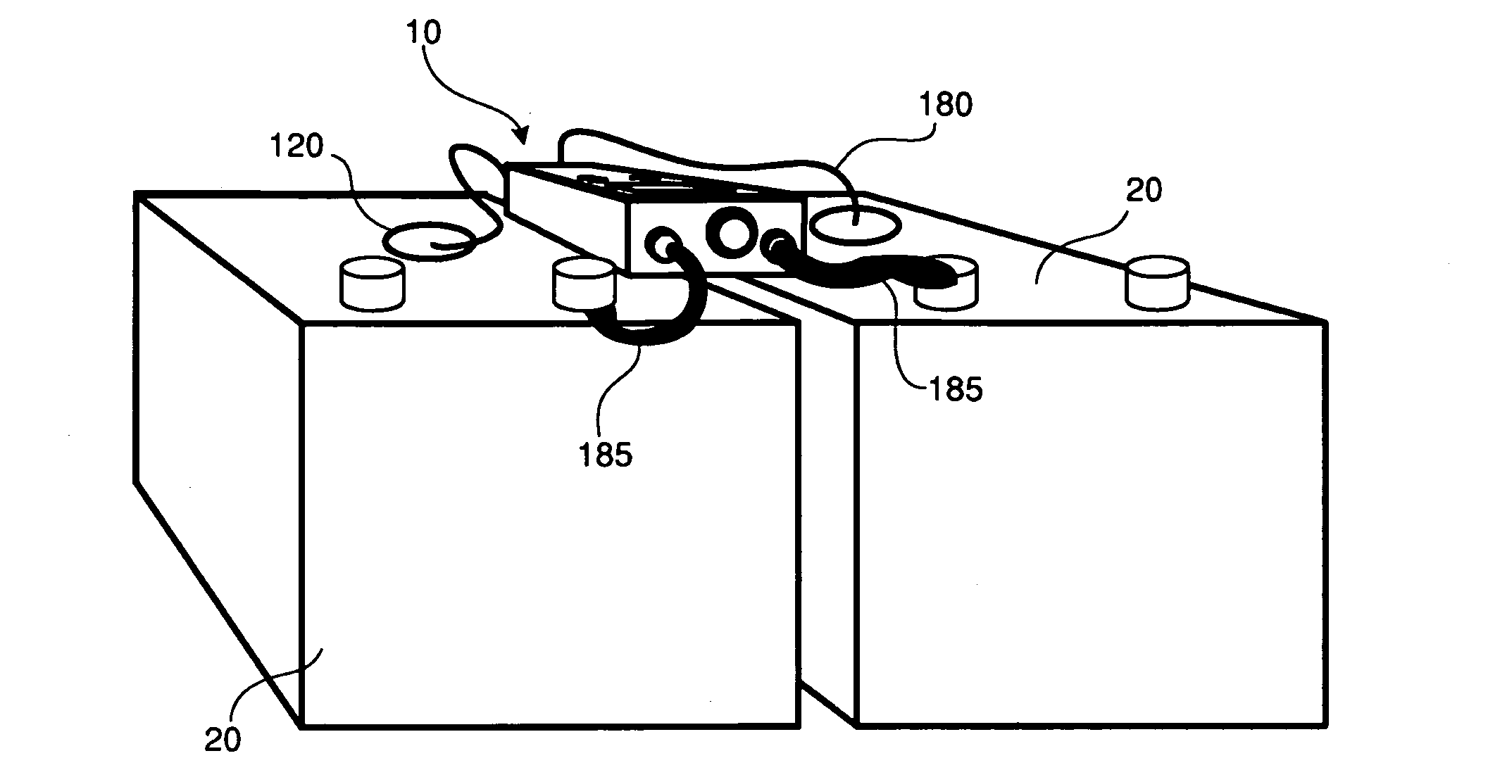
[0032]In a first example, a battery monitoring device 10 may include a body made of plastic, or other suitable corrosion-resistant material, which can be disposed on one or more batteries 20 to which the device is connected in order to monitor the battery. The body is preferably made of a water-resistant material, in order to avoid damage or possible short-circuits when water or electrolyte fluid is supplied to the battery. A fuse 105 may also be provided in the battery monitoring device 10, in order to prevent short-circuiting (see, for example, FIGS. 3A, 3B and 10).

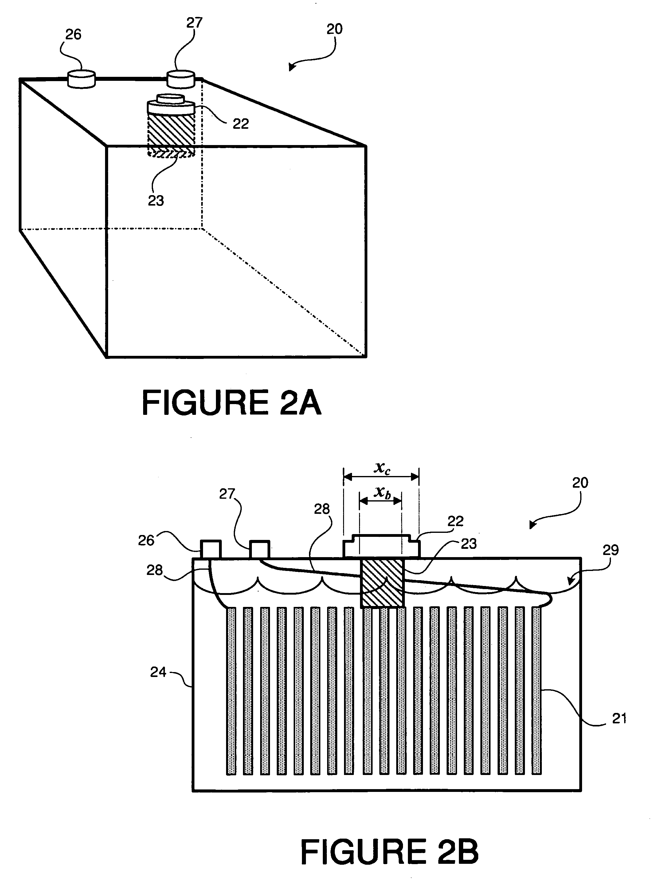
[0033]FIGS. 2A and 2B illustrate a lead acid battery 20 that can be monitored by the present battery monitoring device 10. The battery 20 may include a casing 24, an anode 26 and a cathode 27 each extending from the casing 24, and a valve 23 extending into the battery and having a valve cap 22 for releasing gases (such as hydrogen and oxygen, or water vapor) produced as byproducts of the battery discharge or recharging ...


PUM


Abstract

A battery monitoring device includes a probe for insertion into a valve of a lead acid battery. The probe includes an electrolyte monitoring probe connected to an electrolyte level sensor, and a temperature probe connected to a temperature sensor. The battery monitoring device also includes a display for communicating the temperature and electrolyte level of the lead acid battery, and an LED for indicating that the electrolyte level is low. At appropriate intervals, the battery monitoring device can deliver pulses of electricity to the lead acid battery and counteract sulfation, in order to enhance battery performance and extend the useful lifetime of the battery.

Description

INTRODUCTION[0001]The present discussion relates to a battery monitor for enhancing the operation of lead acid batteries, which can be used with existing batteries, and which can improve charge capacity and extend the useful life of various types of batteries.BACKGROUND[0002]Lead acid batteries are a class of rechargeable electrochemical cells that are widely used in industrial, automotive, marine and household applications. Among the advantages of lead acid batteries are their low cost and their ability to deliver high surge currents (as required for automobile starter motors, for example). In addition, the chemistry of lead acid batteries is relatively uncomplicated, to the extent that the majority of automobile batteries found in cars and trucks worldwide, as well as the batteries that power industrial equipment such as forklifts, are based on plates of common metallic lead immersed in an electrolyte of water and sulfuric acid (see, for example, FIG. 1).[0003]However, certain fac...

Claims


Application Information

Patent Timeline
IPC IPC(8): G01R31/36
CPCB66F9/24H01M10/06H01M10/486H01M10/443H01M10/484H01M10/44Y02E60/10
Inventor SON, HONG K.
Owner SON HONG K
Learn More