Vibration isolator

a technology of vibration isolation and isolator, which is applied in the direction of fluid mattresses, shock absorbers, mechanical equipment, etc., can solve the problems of often limited supply source pressure to 1 mpa or less, and achieve the effects of suppressing the resonant peak, improving the vibration isolation performance, and increasing the load mass

Inactive Publication Date: 2010-01-07
TOKKYOKIKI CORP
View PDF8 Cites 20 Cited by
  • Summary
  • Abstract
  • Description
  • Claims
  • Application Information

AI Technical Summary

Benefits of technology

[0009]In recent years, performance required for a vibration isolation table used for a semiconductor manufacturing apparatus, or an inspection system has been increasingly improved along with the advance in integration degree of a product. For example, in the field of semiconductor, mass production with a line width of 65nm is already possible, and a natural frequency of a pneumatic spring used for a stepper that is a manufacturing apparatus for the mass production is 2 Hz or less. However, for further advances in integration degree and miniaturization, the achievement of a flexible spring having a smaller natural frequency is required. By a measure such as an increase in volume of an air chamber, or the use of a sub tank in order to reduce stiffness of a pneumatic spring of a pneumatic actuator, a vibration isolation effect (vibration isolation performance) for the ground motion disturbance can be improved. However, as a result, responsiveness of the actuator is reduced, and therefore there arises a problem that a vibration suppression effect is reduced for the direct acting disturbance caused by the mass transfer of a stage (112 in FIG. 21) mounted on the vibration isolation table, which contradicts the improvement of the vibration isolation performance. The mounted stage is getting larger and faster in recent years to improve productivity, and therefore achievement of quicker vibration control and position control is required for the vibration isolation stage.
[0010]As is well known, the vibration isolation and vibration control performances of equipment can be improved by the selection and device (synthesis) of a control system for a controlled object, such as velocity, acceleration, pressure, or pressure derivative feedback or feedforward. For example, an application of the acceleration feedback (using the acceleration sensor 106 in FIG. 21) is equivalent to an increase in mass m, and therefore effects of reducing a natural frequency, resonant peak, and the like can be obtained although depending on a condition. If the signal from the ground motion acceleration sensor (108 in FIG. 21) arranged just below the platen 101 is used to apply the feedforward, the vibration isolation performance can be significantly improved in a wide frequency range.
[0016]In summary of an effect of an invention according to Claim 3, the theoretically found dynamic stiffness parameter γ, and a dimensionless dynamic stiffness Kdo (Equation 1), which is a function of γ and a frequency f, are important evaluation indices in determining a condition for configuring the actuator, which effectively completes the present invention. If a load mass supported by the vibration isolator is determined, a design parameter of the pneumatic spring to which the present invention can be applied under the best condition can be specifically and easily selected.
[0021]An effect of an invention according to Claim 8 is that the presence of a condition under which by driving a vacuum actuator with keeping gas flowing during a stationary period, the dynamic stiffness parameter γ and resonant frequency can be made larger and smaller, respectively, is found out. By applying the present invention, performance that can suppress the resonant peak, and achieve both of the excellent vibration isolation performance and the vibration control performance can be obtained.
[0022]By applying the present invention, a precision vibration isolation table capable of obtaining high vibration control performance with keeping excellent vibration isolation performance can be provided. That is, vibration control performance may be improved. For example, along with increases in size and speed of a stage mounted on the vibration isolation table, an increase in excitation force including a high frequency component can be responded to. Also, vibration isolation performance may be improved. For example, floor vibration isolation performance can be improved for advances in integration level and miniaturization of a product by a more flexible spring. A request for the vibration isolation table capable of achieving both of the above performance improvements in the best condition can be responded to. A corresponding effect is extraordinary.

Problems solved by technology

However, from a standard for a pressure container, the supply source pressure is often limited to 1 MPa or less.

Method used


Image

  • Vibration isolator
  • Vibration isolator
  • Vibration isolator

Examples


first embodiment

1. Basic Structure of Precision Vibration Isolation Table According to the Present Invention

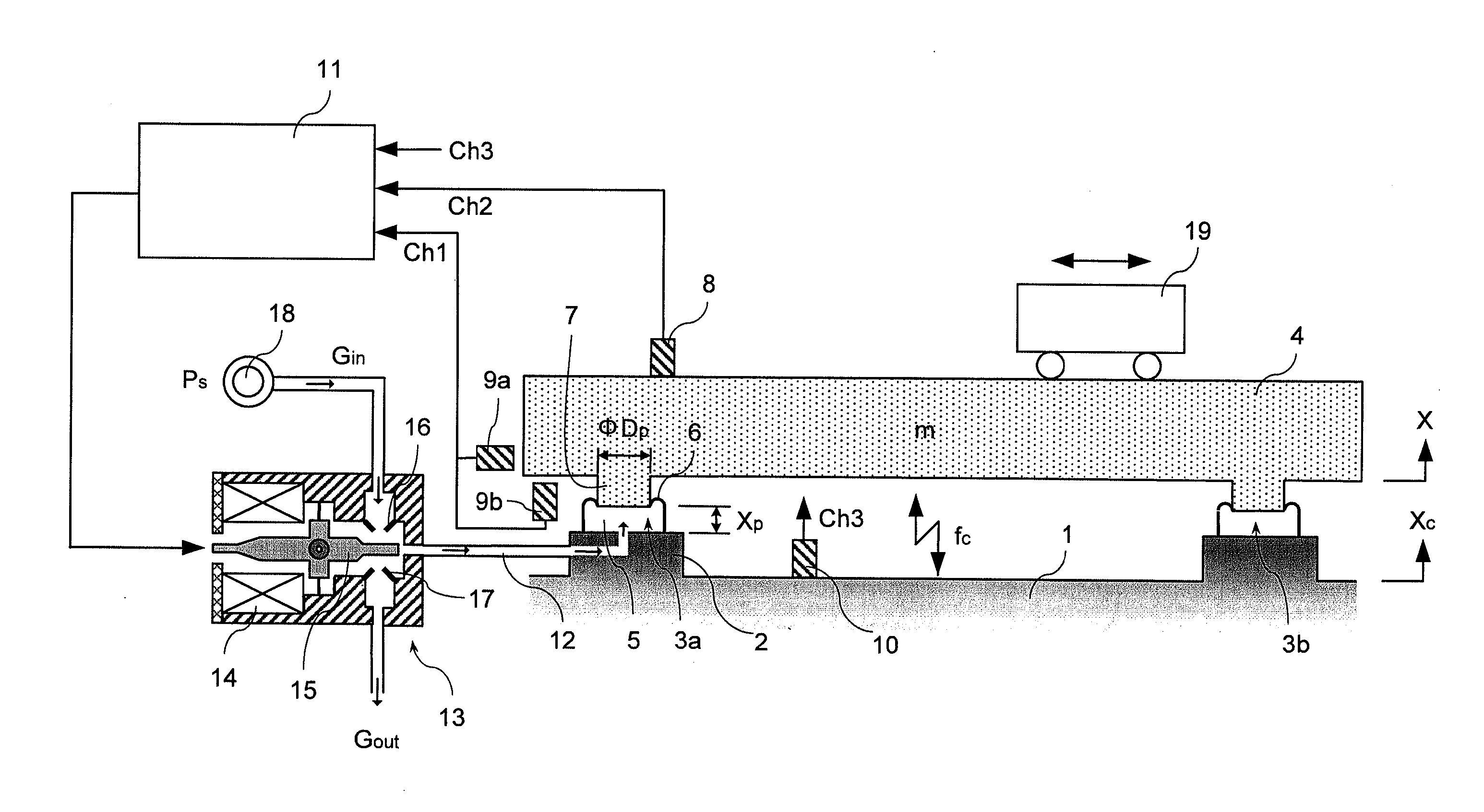
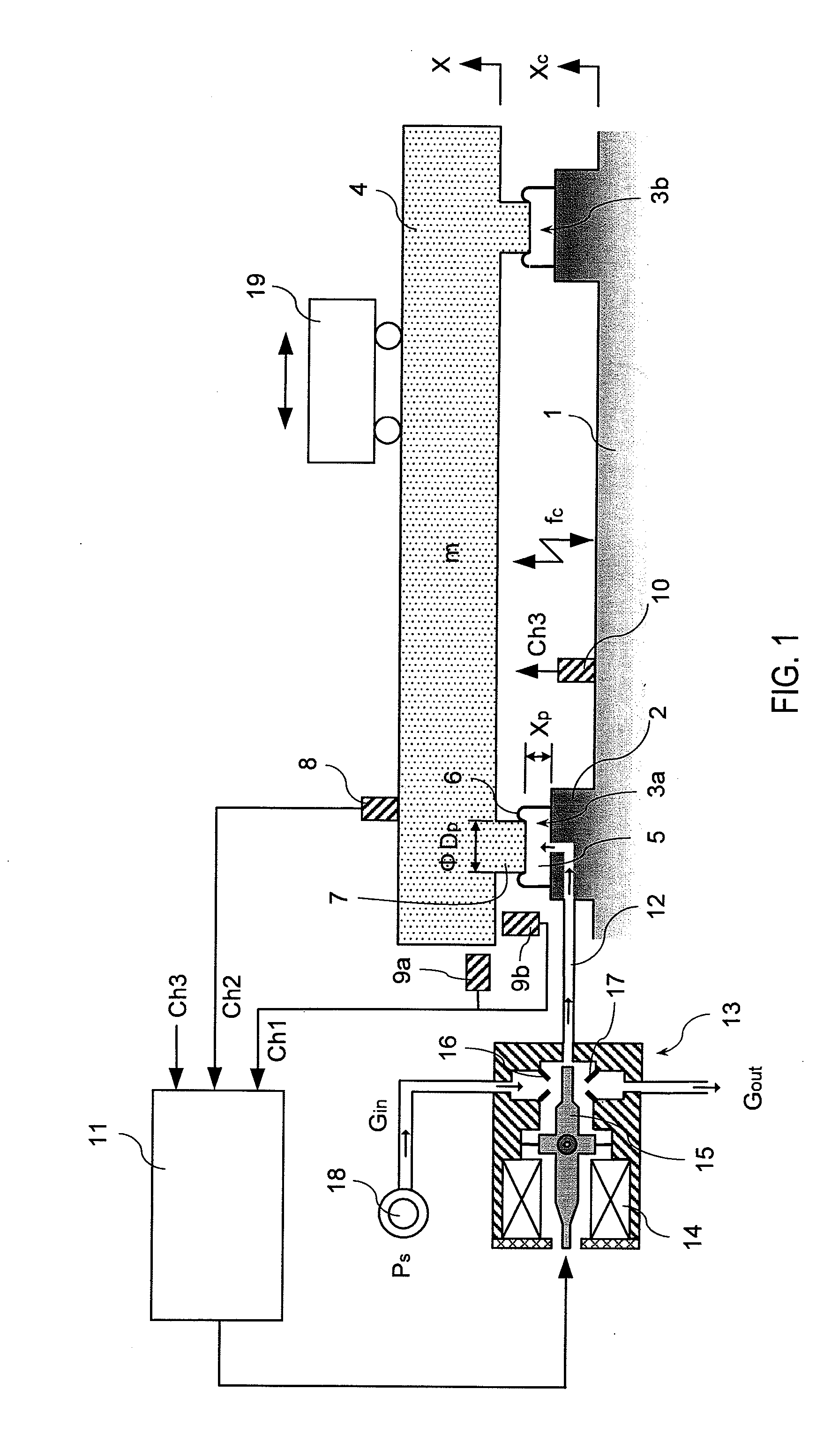
[0046]FIG. 1 is a model diagram illustrating an example of an active precision vibration isolation table according to a first embodiment of the present invention. The precision vibration isolation table is used for precision equipment for which a vibration allowable condition to ensure performance is extremely strict, as used for a semiconductor-related manufacturing apparatus such as an exposure system (stepper), or precision measuring equipment such as a scanning electron microscope, or a laser microscope. That is, the precision vibration isolation table of the present embodiment includes: bases 2 installed on a floor surface 1; and a plurality of sets of pneumatic actuators (pneumatic springs) (only 3a and 3b are illustrated) arranged on upper surfaces of the bases 2, and precision equipment (not shown) is mounted on a platen 4 supported by the pneumatic actuators. Any of the pneumatic act...


PUM


Abstract

There is provided a vibration isolator capable of, (1) vibration isolation performance for ground motion disturbance: vibration isolation for floor vibration, and (2) vibration control performance for direct acting disturbance: suppression of swing due to driving reaction force caused by stage movement, significantly improving the above (2), i.e., the vibration control performance, with keeping the above (1), i.e., the vibration isolation performance, at a high level.

Description

FIELD OF THE INVENTION [0001]The present invention relates to a vibration isolator or the like used for installation of precision equipment such as a semiconductor manufacturing apparatus or precision measuring equipment, and belongs to the field of vibration control that reduces vibration by controlling an inner pressure of a pneumatic spring supporting such a vibration isolating object.BACKGROUND [0002]In various fields such as semiconductor manufacturing, liquid crystal manufacturing, and precision machining, the use of vibration control for shielding / suppressing micro vibration is widely spread. In a microfabrication / inspection apparatus such as a scanning electron microscope, or a semiconductor exposure system (stepper) used in such a process, a strict vibration allowable condition for ensuring performance of the apparatus is required. For the future, there is a trend in which along with further advances in integration degree / miniaturization of a product, increases in speed of ...

Claims


Application Information

Patent Timeline
Patent Type & Authority Applications(United States)
IPC IPC(8): F16F9/02
CPCF16F15/0275
Inventor MARUYAMA, TERUOYASUDA, MASASHI
Owner TOKKYOKIKI CORP
Why Eureka
Try Eureka