
Multi-color hetereodyne interferometric apparatus and method for sizing nanoparticles

a multi-color, interferometric technology, applied in the direction of particle and sedimentation analysis, measurement devices, instruments, etc., can solve the problems of difficult detection of nanoparticles, adverse health effects, inheritable genetic changes,

Inactive Publication Date: 2009-12-31
UNIVERSITY OF ROCHESTER
View PDF20 Cites 89 Cited by
  • Summary
  • Abstract
  • Description
  • Claims
  • Application Information

AI Technical Summary

Benefits of technology

[0017]To achieve the above and other objects, the present invention is directed to a background-free detection approach which gives unsurpassed real-time detection sensitivity for nanoscale particles. The successful detection and class...

Problems solved by technology

For example, inhalation of ultra-fine particles originating from emissions of various kinds can lead to a number of adverse health effects, including inheritable genetic changes.
Because of their small size, nanoparticles are not easy to detect, and it is evident that there is high demand for novel techniques for the reliable detection, characterization, sorting, and tracking of nanoscale particles of various sorts.
Furthermore, as the feature size of integrated circuits becomes increasingly smaller, contamination control of ultrafine particles poses a challenge for the semiconductor industry.
This type of warfare is particularly devastating due to the potential for rapid infection from a small amount of biological agents.
Warfare viruses are especially dangerous because no cures exist against many viruses.
It is, however, very difficult to grow bubbles in a controlled manner, thus the original particle size information is often unavailable.
The cost and complexity of measurements grow quickly as particle size approaches a few tens of nanometers.
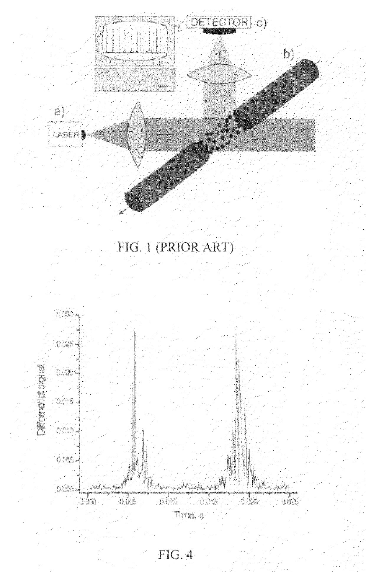
However, the complexity of their setup precludes practical applications of the system in scientific laboratories, as well as in commercial production.
In both of the above-discussed projects, as well as in other optical detection methods, a very strong dependence of the detected signal on particle size is a main obstacle in detecting nanoparticles.
Therefore, the signal to noise ratio decreases very rapidly with particle size.
In order to lower the detectable particle size in currently available instruments from 200 nm to 20 nm, the noise level would have to be reduced by six orders of magnitude, which is not realistic.
These methods, however, are not suitable for single particle identification.
Physical properties cannot be accessed on the nanoscale level, chemical reactions cannot be monitored using such small volumes of reagents.
Raman scattering and fluorescence cross-sections are very small and do not enable enough information to be collected from single nanoparticles.
In principle, X-ray microanalysis can be used to obtain atomic structure of materials, but such method requires expensive equipment, cumbersome sample preparation and lacks high throughput.
Although these methods extend the detection sensitivity to smaller particle sizes, they suffer from other shortcomings which prevent the detection of single nanoparticles in real time.

Method used


Image

  • Multi-color hetereodyne interferometric apparatus and method for sizing nanoparticles
  • Multi-color hetereodyne interferometric apparatus and method for sizing nanoparticles
  • Multi-color hetereodyne interferometric apparatus and method for sizing nanoparticles

Examples


Embodiment Construction

[0031]The present invention will be set forth in detail with reference to the drawings, in which like reference numerals refer to like elements or operational steps throughout.

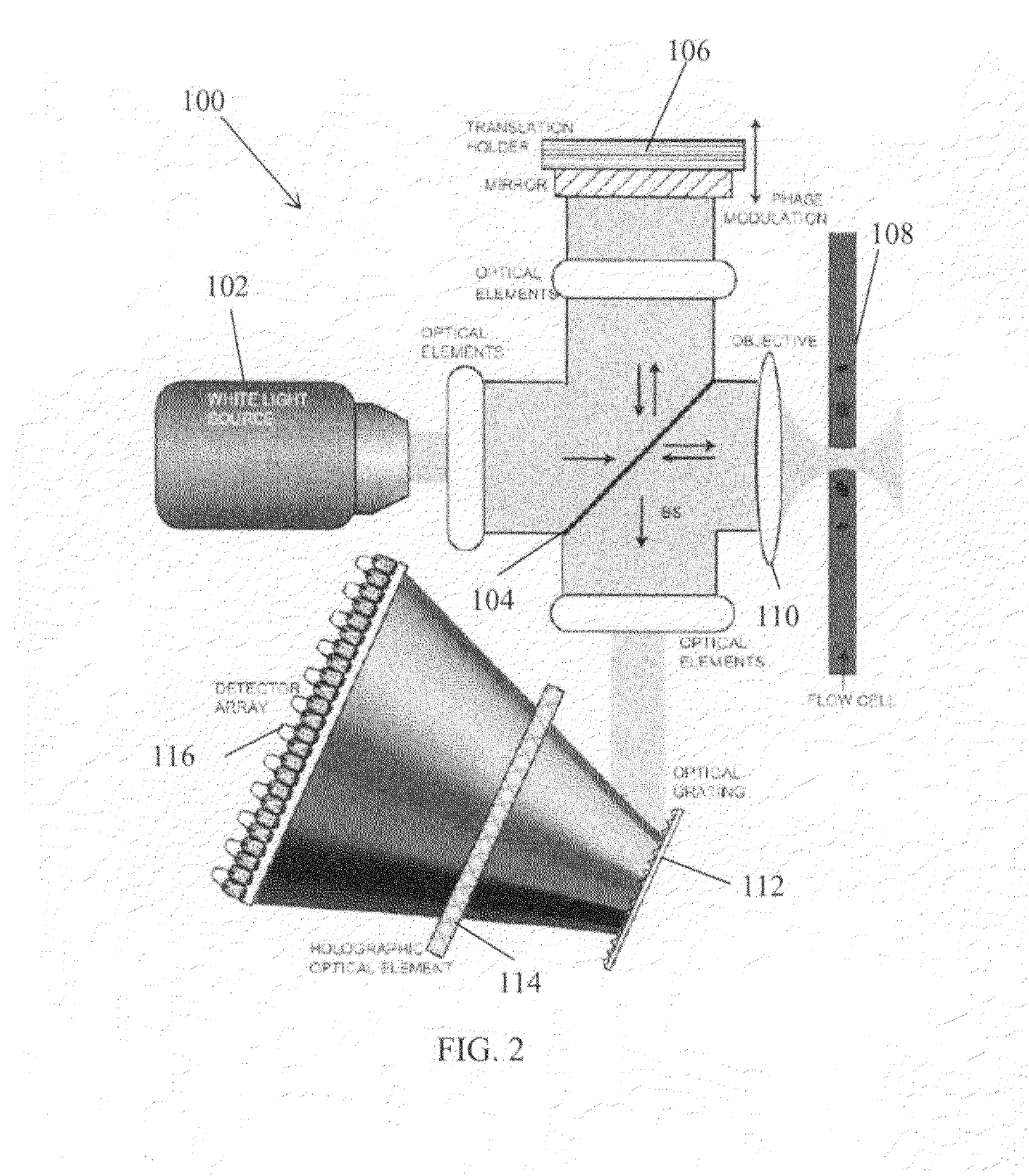
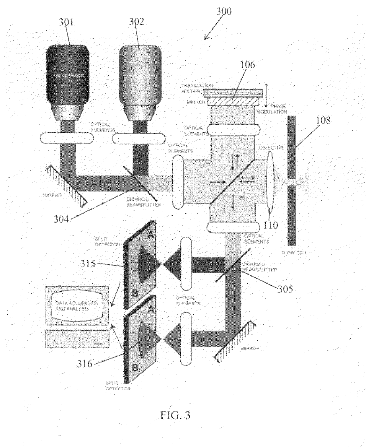
[0032]FIG. 2 illustrates a schematic of a particle detector 100, according to at least one embodiment of the present invention. The excitation light from a light source 102 is split into two parts by a nonpolarizing beamsplitter 104. One part of the beam is reflected back by an oscillating mirror 106, creating a reference beam arm. The other part is focused inside a microfluidic channel 108, containing the particles of interest. The dimensions of the microfluidic channel 108 are comparable to the size of the focus. In one embodiment, the intensity distribution of the focused light across the focus is uniform, so that particles crossing the focus at different parts of the nanochannel are subject to equal illumination conditions.

[0033]Particles are moving through the focus via liquid flow. As a particle travels ...


PUM


Abstract

A nanoparticle sensor is capable of detecting and recognizing single nanoparticles in an aqueous environment. Such sensor may find applications in broad areas of science and technology, from the analysis of diesel engine emissions to the detection of biological warfare agents. Particle detection is based on interferometric detection of multi-color light, scattered by the particle. On the fundamental level, the detected signal has a weaker dependence on particle size (ÿ R3), compared to standard detection methods (ÿ R6). This leads to a significantly larger signal-to-noise ratio for smaller particles. By using a multi-color or white excitation light, particle dielectric properties are probed at different frequencies. This scheme samples the frequency dependence of the particle's polarizability thereby making it possible to predict the composition of the particle material. The detection scheme also employs a heterodyne or pseudoheterodyne detection configuration, which allows it to reduce or eliminate noise contribution from phase variations, which appear in any interferometric measurements.

Description

CROSS-REFERENCE TO RELATED APPLICATIONS[0001]The present application claims the benefit of U.S. Provisional Patent Application No. 60 / 776,953, filed Feb. 28, 2006, whose disclosure is hereby incorporated by reference in its entirety into the present disclosure.STATEMENT OF GOVERNMENT INTEREST[0002]The work leading to the present invention was supported by NSF Grant No. PHS-0441964. The government has certain rights in the invention.FIELD OF THE INVENTION[0003]The present invention is directed to a technique for the detection of nanoparticles, such as viruses, and more particularly to an optical technique using interferometry which does not require knowledge of the dielectric properties of the nanoparticles.DESCRIPTION OF RELATED ART[0004]Particle sizing is used in many areas of science and technology. The food industry, cosmetics, pharmaceuticals, paints and coatings, metals, ceramics, explosives, fireworks and semiconductor industries are just a few places that employ particle size...

Claims


Application Information

Patent Timeline
IPC IPC(8): G01N15/02G01B9/02
CPCG01N15/0211G01N15/1456G01N2015/0038G01N2015/1493G01N2015/0233G01N2015/025G01N2015/1454G01N2015/0088G01N2015/019
Inventor NOVOTNY, LUKASIGNATOVICH, FILIPP
Owner UNIVERSITY OF ROCHESTER
Learn More