
Process and apparatus for molding continuous-fiber composite articles

a technology of composite articles and molding processes, applied in the direction of hollow wall articles, manufacturing tools, machines/engines, etc., can solve the problem of long pipe molded per shot, and achieve the effect of facilitating the fabrication of very long articles

Active Publication Date: 2009-12-17
LOCKHEED MARTIN CORP
View PDF10 Cites 29 Cited by
  • Summary
  • Abstract
  • Description
  • Claims
  • Application Information

AI Technical Summary

Benefits of technology

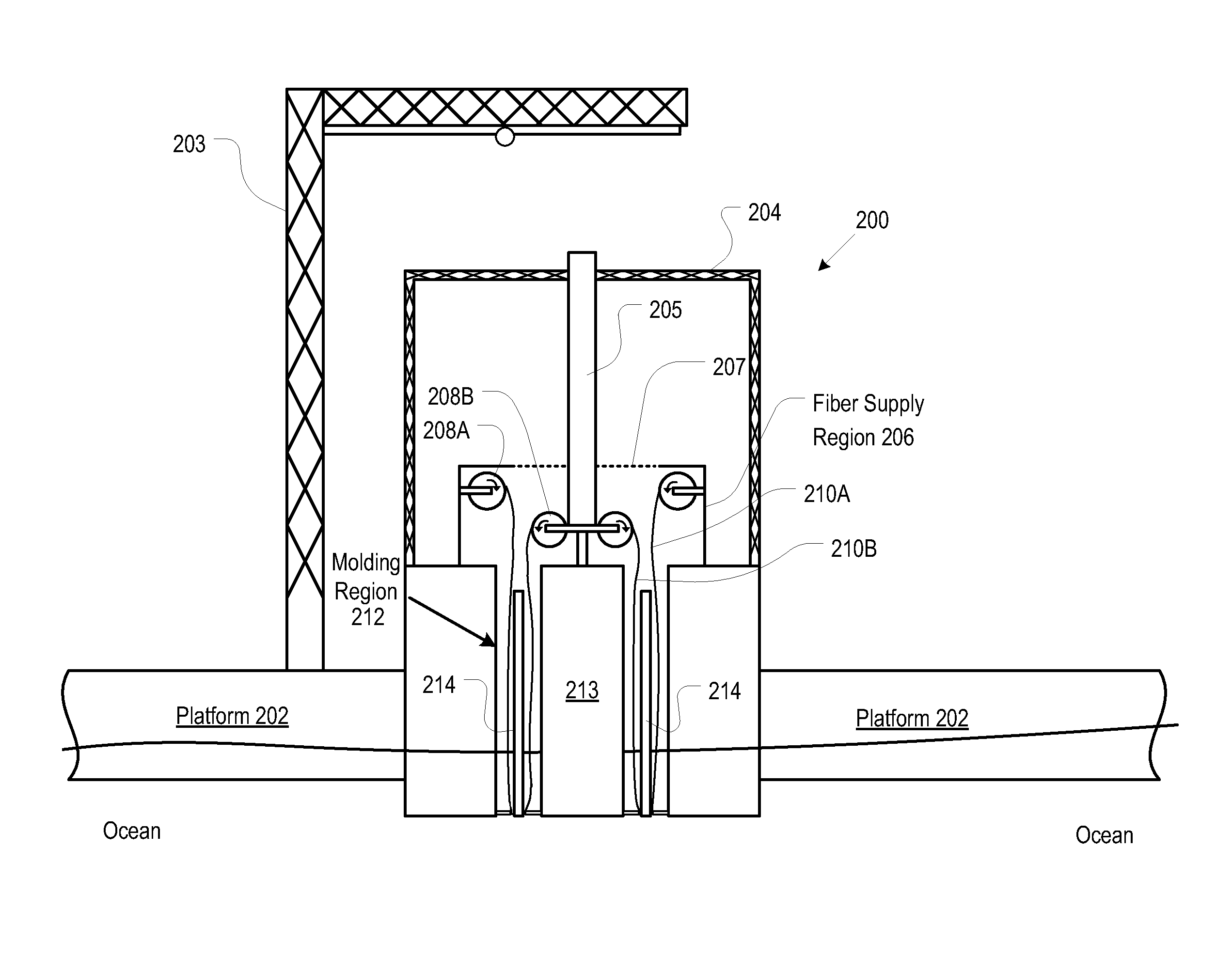
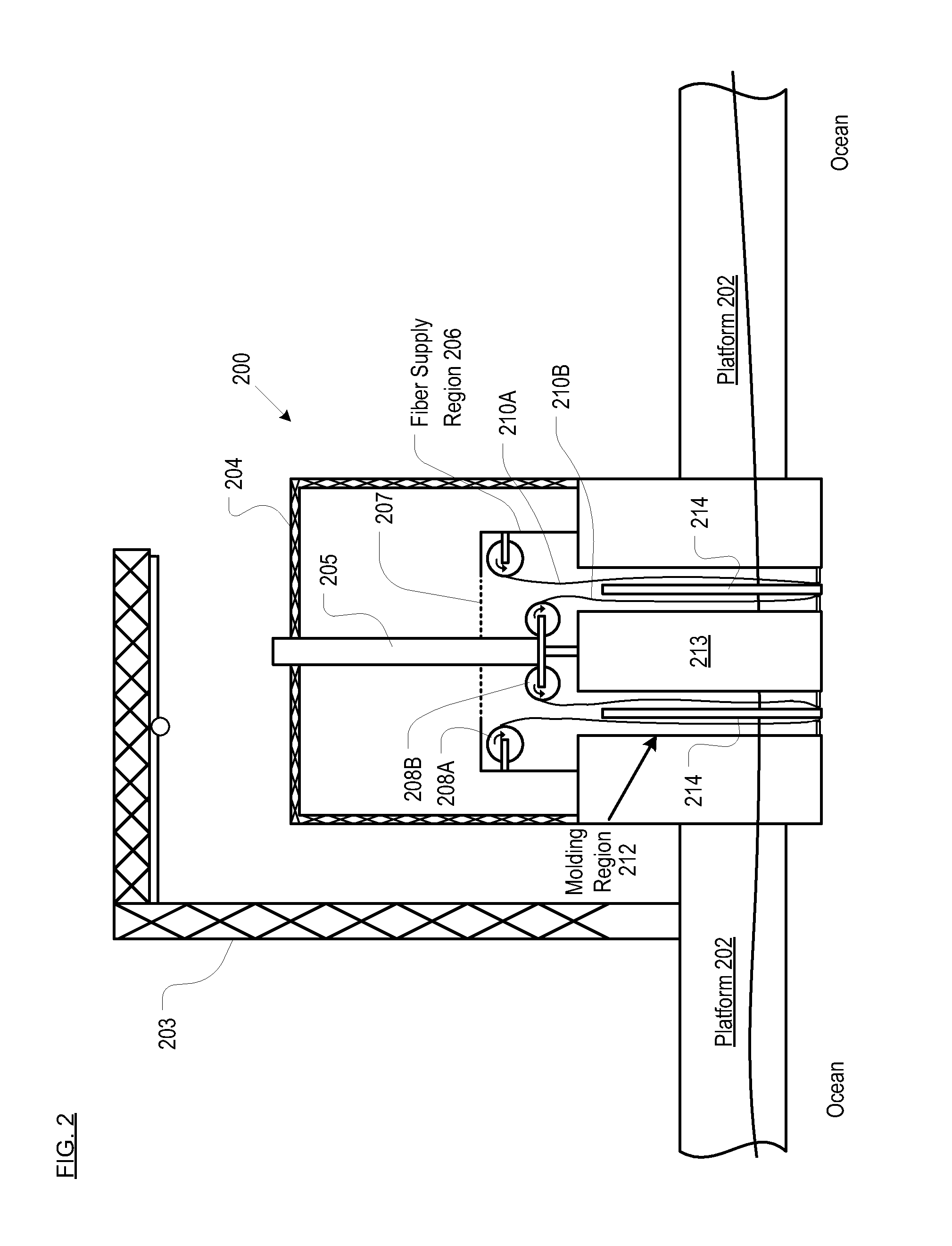
[0012]The current invention provides an apparatus and process to mold very long and very large-diameter articles without some of the costs and disadvantages of the prior art. In particular, and among other advantages, the present method facilitates the fabrication of very long articles on-site, in a series of molding shots on the same article, yet maintains complete continuity of fibers and fiber geometry across the shots within the primary load-bearing portions of the article. As a consequence, although produced as a series of shots, the finished article nevertheless possesses advantageous characteristics of a one-shot molded article.
[0013]In the illustrative embodiment, the apparatus and processes disclosed herein are used to fabricate an OTEC cold water pipe. The fabrication takes place on-site, on a floating ocean platform. In some embodiments, that platform becomes the surface portion of the OTEC plant. This approach eliminates the need to handle and transport what would otherwise be many sections of bulky hollow pipe. Rather, and to great advantage, the process requires the transport of only the raw fabric (e.g., fiberglass, etc.), resin, and discrete-length pultruded core “planks,” all in compact form, to the field location (e.g., platform, barge, etc.).
[0014]For lowest fabrication time and cost, it is desirable to limit the number of molding shots for forming the article (e.g., cold water pipe, etc.). But the fewer the number of shots, the longer the length of pipe molded per shot. The required height of the working area where the pipe is molded is a function, of course, of this unit pipe length.
[0020]Since the density of the liquid resin is similar to water (about 1 g / cc) the aforementioned effect places an absolute limit of about 33 feet on the height of a workpiece that can be made by VARTM. At 33 feet there would, however, be one atmosphere compaction pressure on the composite laminate at the top of the workpiece and zero compaction pressure at the bottom. This would produce very non-uniform laminate properties, such as, for example, fiber volume fraction. This second effect limits the practical working heights for a single “shot” of VARTM to about 15 feet. To fabricate a cold water pipe having a length of 3000 feet would require an unacceptably high 200 shots, if each shot produced a pipe section having a length of only 15 feet.
[0023]To facilitate the positioning of fabric within the molding region, a vacuum is drawn “behind” the inner soft tool and the outer soft tool (i.e., in the region between the soft tool and the nearest hard surface). The vacuum causes the inner soft tool to move toward the hard inner surface and the outer soft tool to move toward the hard outer surface. Fabric from the rolls is then fed into the molding region, along with a core material. The core material forms the core of a “sandwich” pipe wall and the fabric forms the face sheets of that sandwich. Specifically, fabric is disposed between the inner soft tool and the core, and fabric is also disposed between the outer soft tool and the core. In some embodiments, a resin distribution material (to assist in spreading the resin throughout the fabric) is pulled into the molding region along with the fabric.
[0024]After the fabric and core are in place in the molding region, the vacuum established behind the soft tools is released. An inner and outer vacuum seal are activated at the bottom of the molding region to seal the soft tools to that portion of the workpiece that has already been formed during a previous molding operation (i.e., a previous shot). A vacuum is developed on the “other” side of the soft tools (where the still-dry fabric is disposed) to withdraw air from the fabric in the molding region, which minimizes the void content of the resulting laminate. To avoid having to create a gas-tight seal between the fiber supply region and the molding region (over the dry, porous fabric, where creating such a seal would be particularly difficult or perhaps even impossible), the fiber supply region, as well as the molding region, are in fluidic communication with one another and are both placed under vacuum.

Problems solved by technology

But the fewer the number of shots, the longer the length of pipe molded per shot.

Method used


Image

  • Process and apparatus for molding continuous-fiber composite articles
  • Process and apparatus for molding continuous-fiber composite articles
  • Process and apparatus for molding continuous-fiber composite articles

Examples


Embodiment Construction

[0039]Definitions. The terms appearing below are provided with the follow explicit definitions for use in this description and the appended claims.[0040]Continuous-fiber composite means a fiber composite in which fibers are continuous throughout that the composite, as opposed to being chopped or short (i.e., discontinuous).[0041]Shot refers to the amount of resin that is required to fill a mold cavity. A “multi-shot” article requires multiple, sequential resin fills and cures within the mold cavity.[0042]Workpiece means the structure that is produced or the assemblage (e.g., core, fiber, resin) that will form that structure in a single shot in the molding region. In the context of multi-shot articles, the workpiece therefore represents a portion or segment of the final composite article (e.g., a segment of the cold water pipe, etc).[0043]Continuity of fiber means that there is no discontinuity or break in fibers between the workpieces that compose a multi-shot composite article. To ...


PUM

PropertyMeasurementUnit
Lengthaaaaaaaaaa
Pressureaaaaaaaaaa
Densityaaaaaaaaaa

Abstract

A process and apparatus for multi-shot, liquid-resin-molding of continuous-fiber composite articles is disclosed. The process involves the step-wise fabrication of an article wherein continuity of the fibers is maintained between the multiple workpieces of the finished composite article.

Description

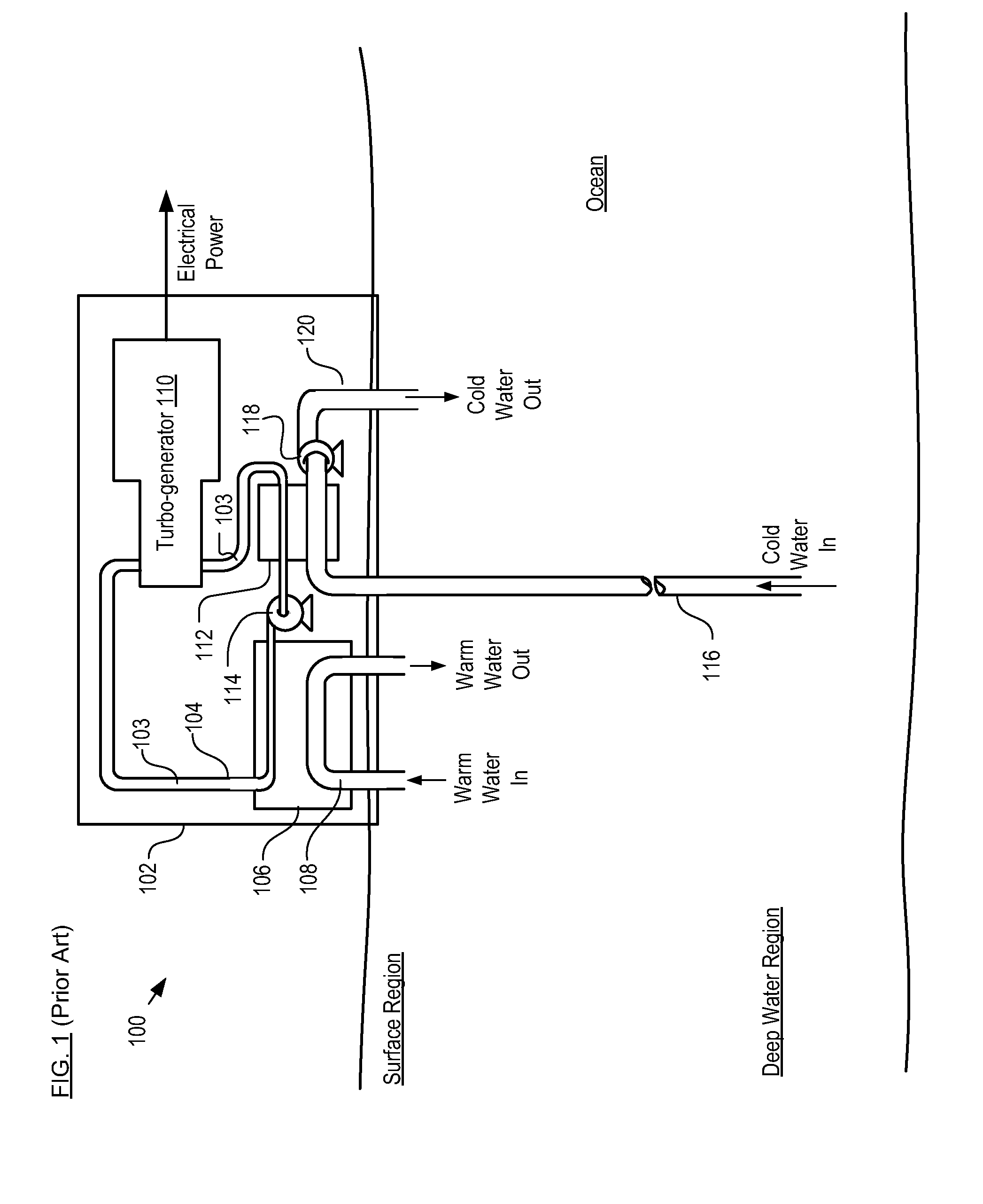
STATEMENT OF RELATED CASES[0001]This case claims priority of U.S. Provisional Patent Application Ser. No. 61 / 061,204 filed Jun. 13, 2008, which is incorporated herein.FIELD OF THE INVENTION[0002]The present invention relates to the production of long-length, continuous-fiber composite materials and structures.BACKGROUND OF THE INVENTION[0003]There is growing interest in Ocean Thermal Energy Conversion (“OTEC”) systems as a means of carbon-free electric power generation. OTEC systems exploit the temperature difference between the warm surface waters of tropical seas and the cold waters of the deep ocean to generate electricity.[0004]An OTEC system, such as closed-loop OTEC system 100 depicted in FIG. 1, usually resides on floating platform, ship, or barge 102. Key components of system 100 include closed-loop conduit 104, evaporator 106, warm water pipe 108, turbo-generator(s) 110, condenser 112, and cold water pipe 116.[0005]Closed-loop conduit 104 contains working fluid 103, such as...

Claims


Application Information

Patent Timeline
IPC IPC(8): B29C43/34B29C70/16
CPCB29C70/443B29C70/446Y02E10/34B29D23/001B29L2023/22B29C70/50F03G7/05Y02E10/30
Inventor MILLER, ALAN K.BAILEY, STEPHEN L.ROSARIO, JR., THEODORE
Owner LOCKHEED MARTIN CORP
Learn More