
Apparatus and method for removing unburned carbon from fly ash

a technology of unburned carbon and apparatus, which is applied in the direction of solid waste management, sustainable waste treatment, transportation and packaging, etc., can solve the problems of increasing facility cost and difficulty in adjusting the required capacity of the system, and achieve stable performance adjustment and maintenance. the effect of suitably suitability and stable performance adjustmen

Inactive Publication Date: 2009-12-17
TAIHEIYO CEMENT CORP
View PDF15 Cites 1 Cited by
  • Summary
  • Abstract
  • Description
  • Claims
  • Application Information

AI Technical Summary

Benefits of technology

[0011]The present invention has been made in consideration of the above problems, and the object thereof is to provide an apparatus and a method for suppressing facility cost and realizing stable performance adjustment depending on property of fly ash.
[0027]As described above, with this invention, when removing unburned carbon from fly ash, increase of facility cost can be suppressed and stable performance adjustment depending on property of fly ash may be achieved. In addition, by the effect of producing new surface of fly ash particle, when the fly ash is added to cement and is hardened with the cement, the fly ash can be more solidly reacted with cement hydrate.

Problems solved by technology

However, in the above-mentioned conventional method for removing unburned carbon from fly ash, a comparatively large submerged agitator is used to add shearing force to fly ash slurry, which causes a problem of increased facility cost.
In addition, generally, one submerged agitator as described above is installed to a system for removing unburned carbon, which causes another problem that it is difficult to adjust the required capacity of the system depending on property of fly ash.

Method used


Image

  • Apparatus and method for removing unburned carbon from fly ash
  • Apparatus and method for removing unburned carbon from fly ash
  • Apparatus and method for removing unburned carbon from fly ash

Examples


Embodiment Construction

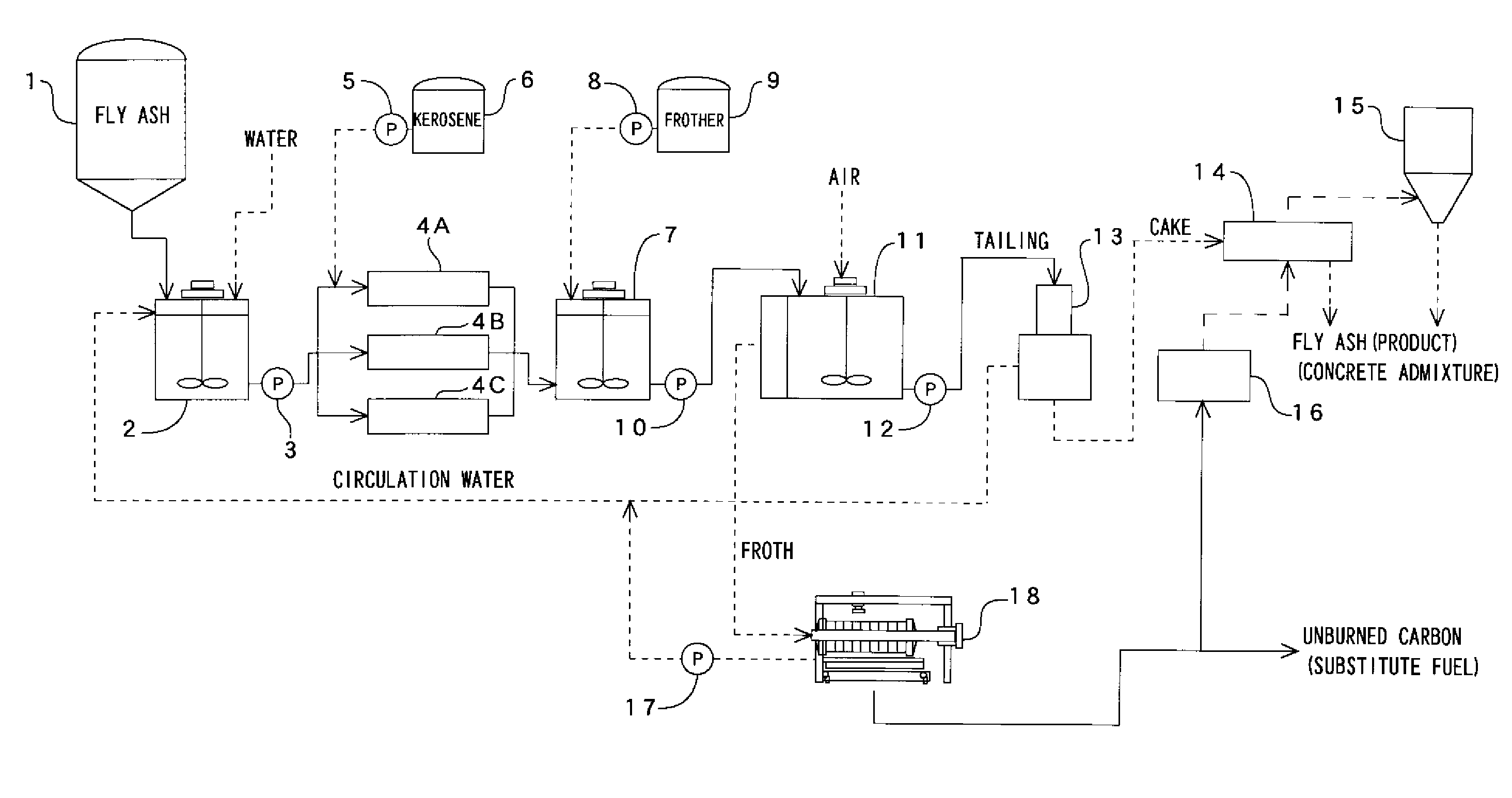
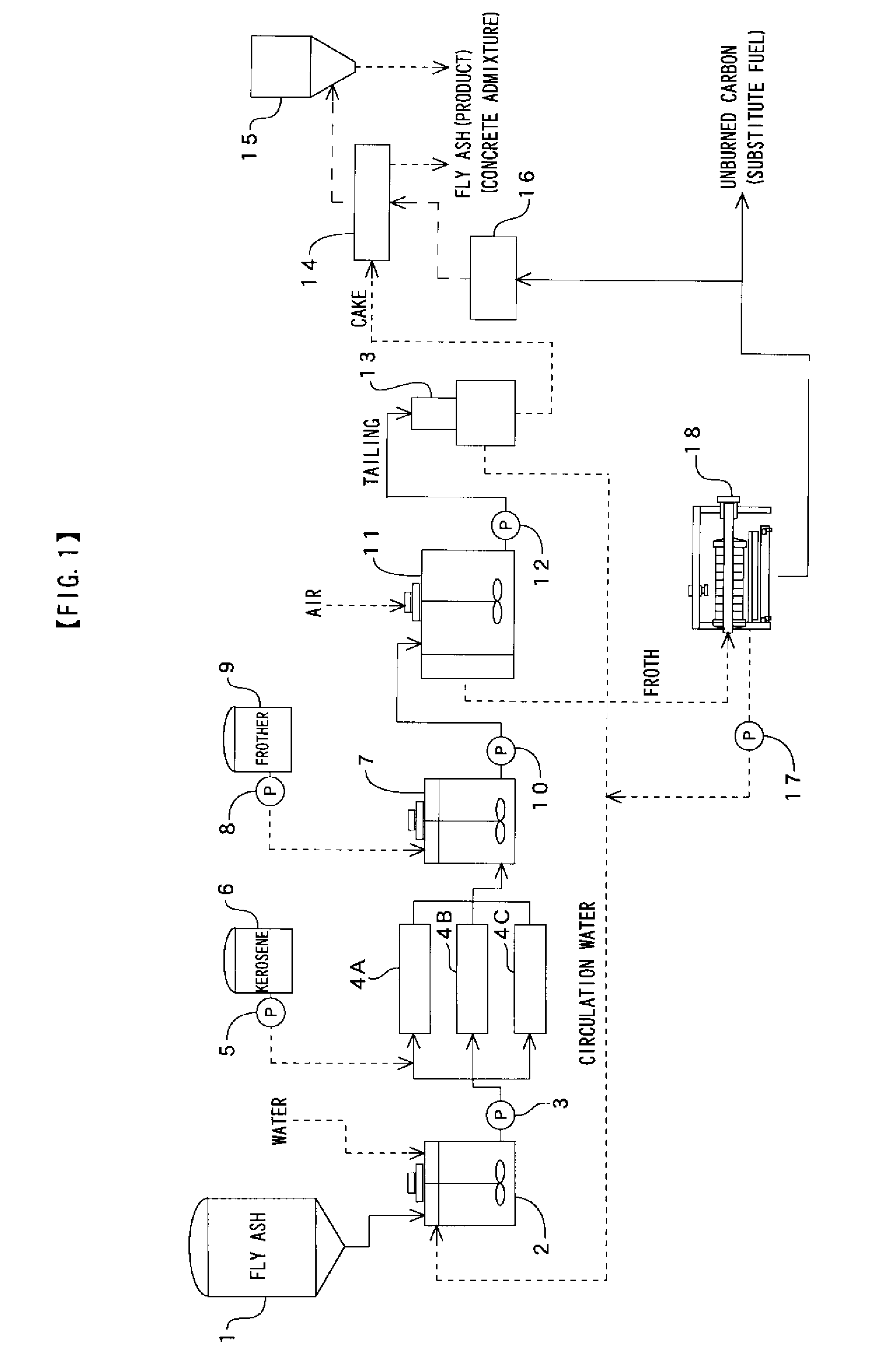
[0034]FIG. 1 shows an example of the system composition for enforcing an apparatus and a method for removing unburned carbon from fly ash according to the present invention, and the system roughly comprise a fly ash tank 1, a slurry tank 2 for adding water to fly ash fed from the fly ash tank 1 to generate slurry, a static-type mixers 4 (4A-4C) that apply shearing force to the slurry and a collector after adding the collector to the slurry to modify the surface of unburned carbon and so on, a flotation machine 11 that separates the unburned carbon by adding frother to the slurry, generating air bubbles, making the unburned carbon of fly ash adhere to the air bubbles and rise, a solid / liquid separator 13 for solid / liquid separating tailing from the flotation machine 11, a drier 14 for obtaining dried fly ash (product) by drying cake from the solid / liquid separator 13, a filter press 18 for solid / liquid separating froth from the flotation machine 11 to obtain unburned carbon, and so o...


PUM

PropertyMeasurementUnit
weight percentaaaaaaaaaa
shearing forceaaaaaaaaaa
pressure lossaaaaaaaaaa

Abstract

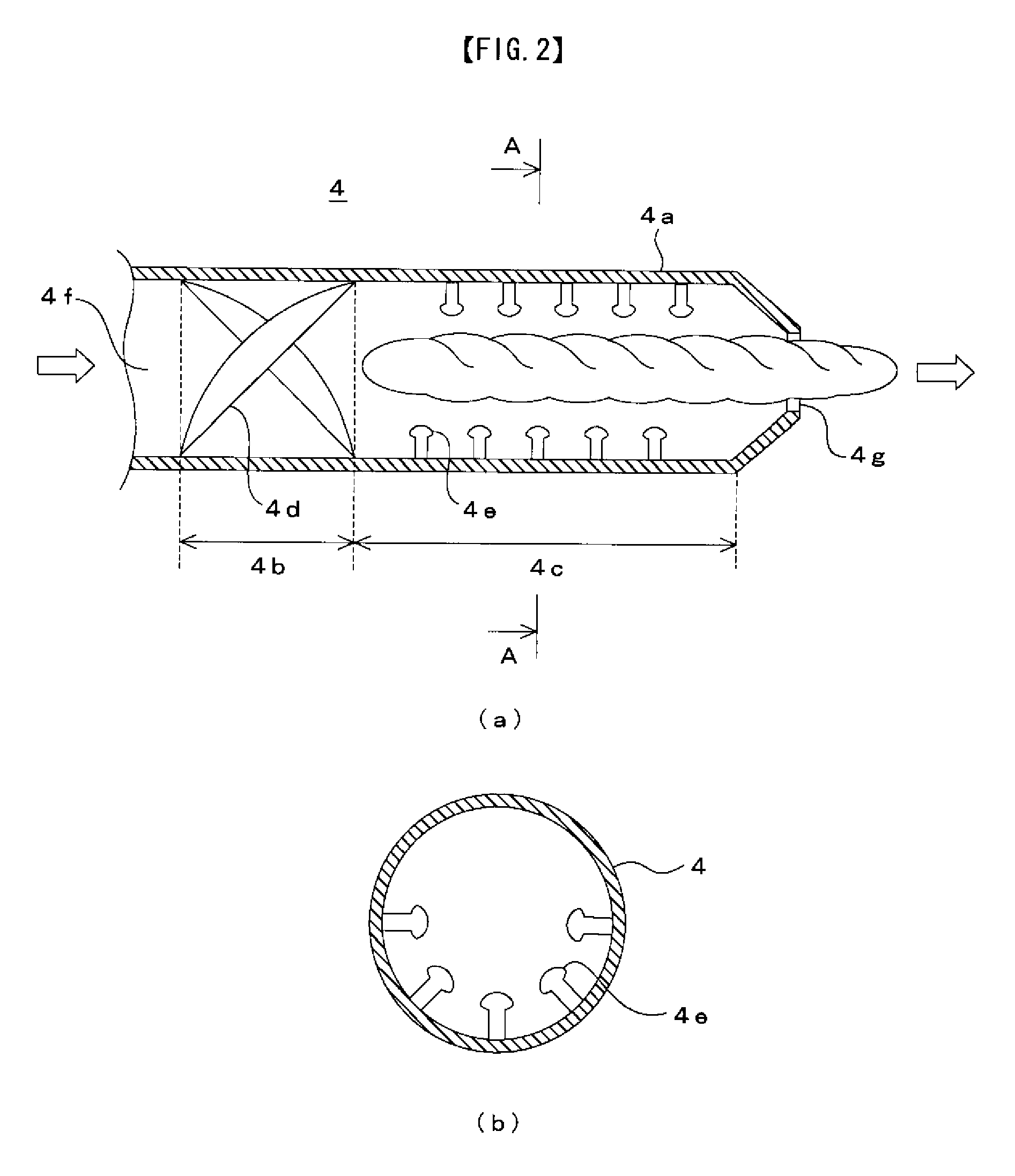
An apparatus and a method for removing unburned carbon from fly ash capable of suppressing facility cost and stably conducting performance adjustment depending on property of the fly ash. The method comprises the steps of: adding water to fly ash to produce slurry; adding collector to the slurry, feeding the slurry and the collector to a static-type mixer 4, a venturi pipe 24 or the like to add shearing force to them; adding frother to them to generate air bubbles; and adhering unburned carbon of the fly ash to the air bubbles to raise the unburned carbon. The frother and air can be fed to the static-type mixer or the like together with the slurry and the collector. Depending on the change in property of the fly ash, the number of the static-type mixers or the like used in series can be increased or decreased, and depending on required capacity, the number of the static-type mixers or the like used in parallel may be increased or decreased. The static-type mixer may comprise a guide vane chamber 4b with plurality of guide vanes 4d for converting the slurry and the like, which are fed to the chamber, to spiral flow, and a current cutter chamber 4c with plurality of mushroom-shaped projections 4e for adding shearing force to the slurry and the like.

Description

CROSS-REFERENCE TO RELATED APPLICATIONS[0001]The present application claims priority to International Application No. PCT / JP2006 / 323656 which was filed on Nov. 28, 2006 and claims priority to Japanese Patent Application No. 2005-353097 filed Dec. 7, 2005.STATEMENT RE: FEDERALLY SPONSORED RESEARCH / DEVELOPMENT[0002]Not ApplicableBACKGROUND OF THE INVENTION[0003]1. Technical Field of the Invention[0004]The present invention relates to an apparatus and a method for removing unburned carbon from fly ash, and more particularly to an apparatus and a method for efficiently removing unburned carbon from fly ash generated in coal firing power plants and so on, and effectively using the removed unburned carbon and the fly ash from which unburned carbon is removed.[0005]2. Description of the Related Art[0006]Fly ash generated in coal firing power plants etc. is used for materials for cement and artificial lightweight aggregates, concrete admixture, etc. However, when fly ash is used as concrete...

Claims


Application Information

Patent Timeline
Patent Type & Authority Applications(United States)
IPC IPC(8): B03D1/02B09B3/00B09B5/00
CPCB01F5/0612B01F5/0614B01F2005/0621B01F2005/0636B03D1/247C04B18/08B03D1/02B03D1/14C04B20/02Y02W30/91B01F25/4312B01F25/4317B01F25/4314B01F25/431971B09B5/00C02F11/00
Inventor SAITO, SHINICHIROABE, KAZUOMATSUO, KAZUYOSHI
Owner TAIHEIYO CEMENT CORP
Learn More