Endovascular graft including substructure for positioning and sealing within vasculature

Inactive Publication Date: 2009-12-03
LIFESHIELD SCI
View PDF19 Cites 160 Cited by
  • Summary
  • Abstract
  • Description
  • Claims
  • Application Information

AI Technical Summary

Benefits of technology

[0013]In one embodiment of the present invention, a sleeve is affixed to the inside of the graft bifurcation or crotch of a bifurcated graft, and assists in positioning the graft and its components within vasculature. An associated grafting system further includes a contralateral guide wire having a hook or bulbous portion on a terminal end of the guide wire. The hook or bulbous portion facilitates the snaring of the contralateral guide wire with a snare loop. The graft sleeve provides a pathway for the contralateral guide wire through the graft such that a physician may manipulate the contralateral guide wire to position the bifurcated graft at a repair site. Once the modular graft is positioned at the repair site, leg extensions may be assembled to the graft ipsilateral and contralateral leg stumps.
[0015]In a further embodiment of the present invention, an improved stitching pattern for attaching graft components is provided. The improved stitching pattern involves at least two double loop knots and at least two suture loops around structure to be attached to a graft, the structure being anchored with a running stitch having threaded loops and double loop knots. The stitching pattern provides a secure connection if one portion of the suture is severed or damaged.
[0017]A second aspect of the sealing member is embodied in a tufted PET fabric formed from a non-woven web of loose fibers attached to the graft member walls by a suture thread, wherein the non-woven web has an in-air thickness of approximately 0.01 in. and a compressed thickness in the range of 0.007 in. to 0.008 in., and a width of approximately 5 cm. The non-woven tufted web provides a continued circumferential surface around the attachment member to assist in blood clotting of leaks and promoting tissue growth.
[0018]In still another embodiment of the present invention, the graft system includes a mating structure that releasably attaches the ipsilateral member and the contralateral members of a bifurcated graft, wherein the members are attached during deployment, and separated after deployment, thus allowing post-insertion positioning. The inferior members or limbs of a graft are connected together to improve control, stability, and column stiffness of the graft when accessing the contralateral artery.
[0020]In a second aspect, the mating structure includes a suture material releasably configured to form a running stitch pattern that attaches the ipsilateral member and contralateral member. The suture begins at the graft bifurcation and is stitched in-and out through the ipsilateral member and contralateral member, a release wire being configured to disengage the members, thereby allowing positioning of the graft members at a vessel bifurcation.

Problems solved by technology

For example, various types of aneurysms or other deteriorative diseases may affect the ability of the lumen to conduct fluids and, in turn, may be life threatening.
For repair of vital lumens such as the aorta, surgical repair is significantly life threatening or subject to significant morbidity.
Although the use of modular endovascular grafts minimize some of the difficulties, there are still drawbacks associated with the current methods.
Where it is desirable to repair vasculature with a device that is assembled in situ, it can be difficult to accomplish positioning various components of the repair device within the diseased vessel.
Moreover, attachment systems typically used for anchoring modular grafts and unibody grafts to a vessel wall can form improper seals and result in fluid leaks.
A reoccurring difficulty relates to exposing certain of the modular junction attachment sites to continuous blood flow.
Other drawbacks associated with endovascular grafts involve providing components having a secure attachment to the main graft.
The femoral delivery approach for bifurcated grafts has its limitations.
If the bifurcated graft is deployed close to the natural bifurcation of the aneurysm, there is potential that the inferior members will need to take a sharp bend in order to conform to the aortic anatomy.
Positioning the bifurcated graft, using this approach, has resulted in kinking and twisting of the inferior graft members.
These limitations may result in patency problems, and added stress to the sutures holding the implant components together.

Method used


Image

  • Endovascular graft including substructure for positioning and sealing within vasculature
  • Endovascular graft including substructure for positioning and sealing within vasculature
  • Endovascular graft including substructure for positioning and sealing within vasculature

Examples


Embodiment Construction

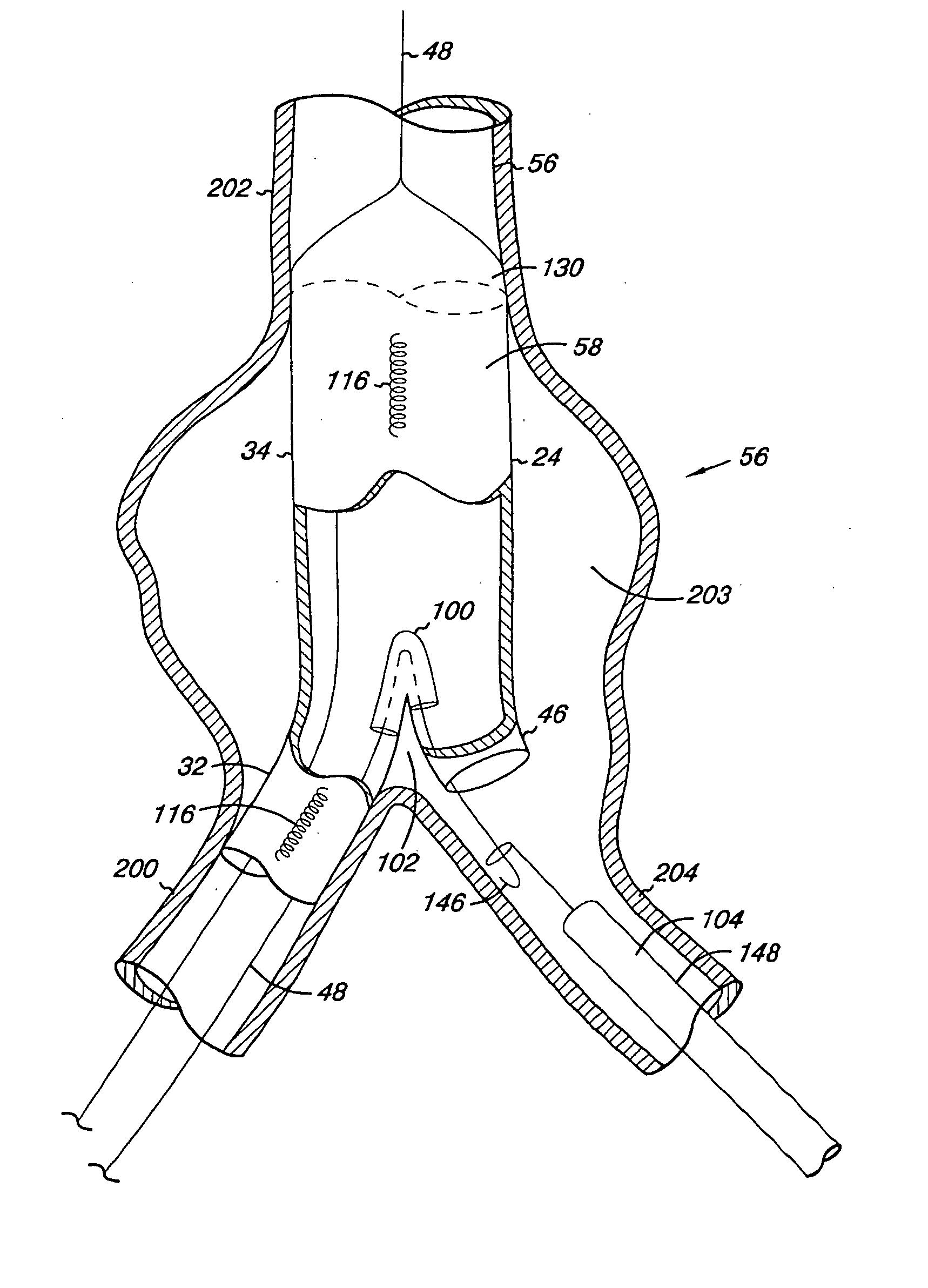
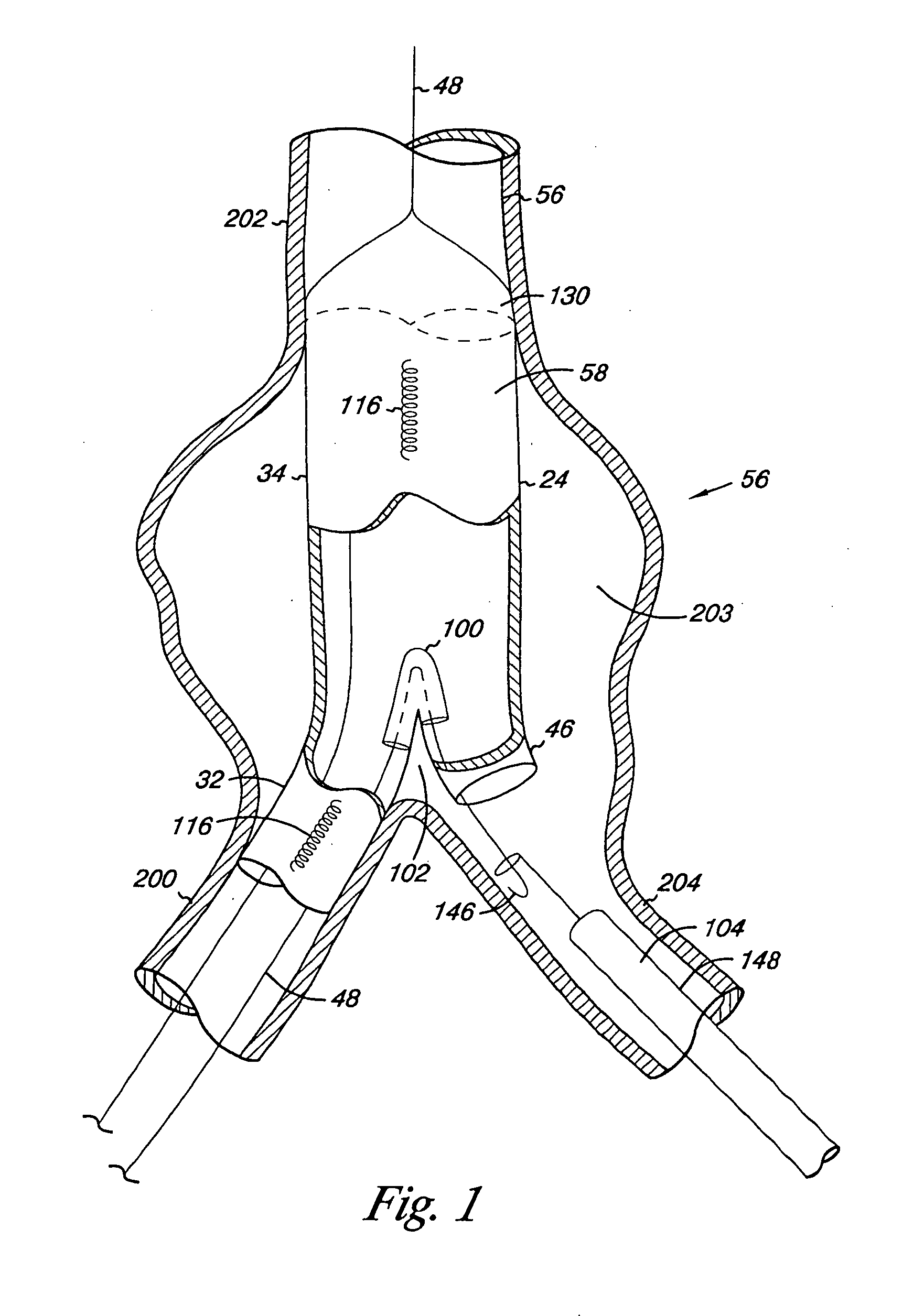
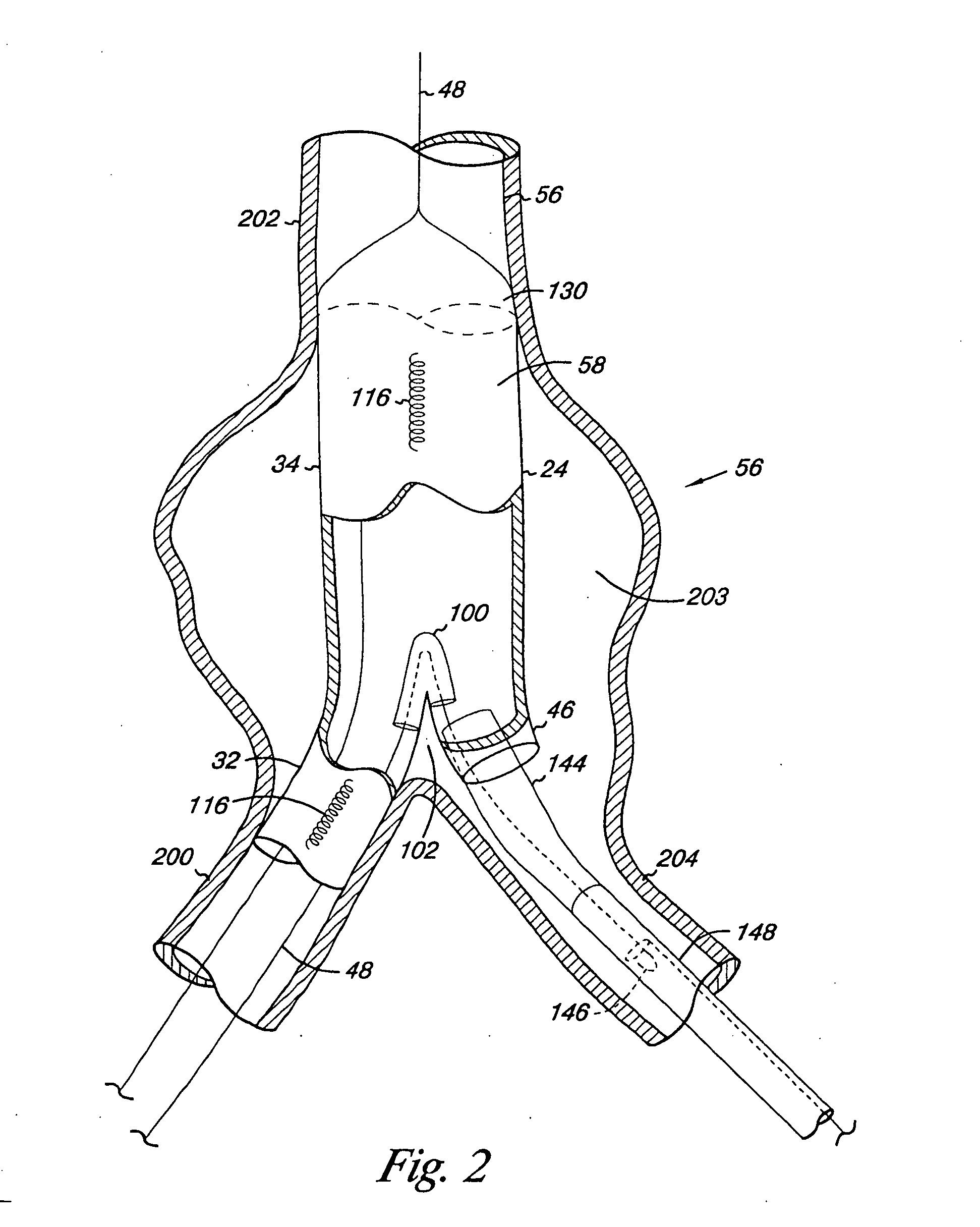
[0038]As shown in the drawings and for the purpose of illustration the invention is embodied in an endovascular graft for repairing vasculature. A positioning mechanism is provided for facilitating the positioning of a graft within vasculature. The graft may include a sealing mechanism and attachment mechanisms to secure the graft within the vasculature. One of the disclosed features involves the use of a sleeve incorporated into the graft which is used in combination with a wire for placement of the graft across a vascular bifurcation such as the aortic bifurcation. Additionally, the graft includes a self-sealing means that compensates for oversizing of a vessel wall. The superior and inferior graft portions may be provided with improved leak tight sealing tufts. Furthermore, the graft may include a pattern for stitching a stent or other structure to members of a graft for securing the members together.

[0039]Those skilled in the art will recognize many of the disclosed components c...


PUM


Abstract

An endovascular graft having an improved positioning mechanism capable of positioning and securing a bifurcated graft into a bifurcated vessel described. The graft can include a sleeve affixed to graft that is used in combination with a contralateral wire loop for placement of the graft within vasculature. The graft may include a structure for post deployment positioning into the bifurcated aneurysm area. Furthermore, the endovascular graft may be configured to form a sealing pocket that expands with induced fluid pressure and prevents fluid leaks at an attachment site.

Description

BACKGROUND OF THE INVENTION[0001]The present invention relates generally to vasculature repair and more particularly to devices for accomplishing positioning and securement of a repair device at an interventional site.[0002]It is well established that various fluid conducting body or corporeal lumens, such as veins and arteries, may deteriorate or suffer trauma so that repair is necessary. For example, various types of aneurysms or other deteriorative diseases may affect the ability of the lumen to conduct fluids and, in turn, may be life threatening. In some cases, the damage to the lumen is repairable only with the use of prosthesis such as an artificial vessel or graft.[0003]For repair of vital lumens such as the aorta, surgical repair is significantly life threatening or subject to significant morbidity. Surgical techniques known in the art involve major surgery in which a graft resembling the natural vessel is spliced into the diseased or obstructed section of the natural vesse...

Claims


Application Information

Patent Timeline
IPC IPC(8): A61F2/06
CPCA61F2/07A61F2/954A61F2002/065A61F2/89A61F2002/075A61F2002/8486A61F2002/9511A61F2002/067
Inventor FAWZI, NATALIE V.BARKMAN, KIMBERLYECKERT, ROBIN W.ESCANO, ARNOLD M.REINHARDT, RODNEY H.VINCENT, ROBERT A.
Owner LIFESHIELD SCI
Why Eureka
Try Eureka