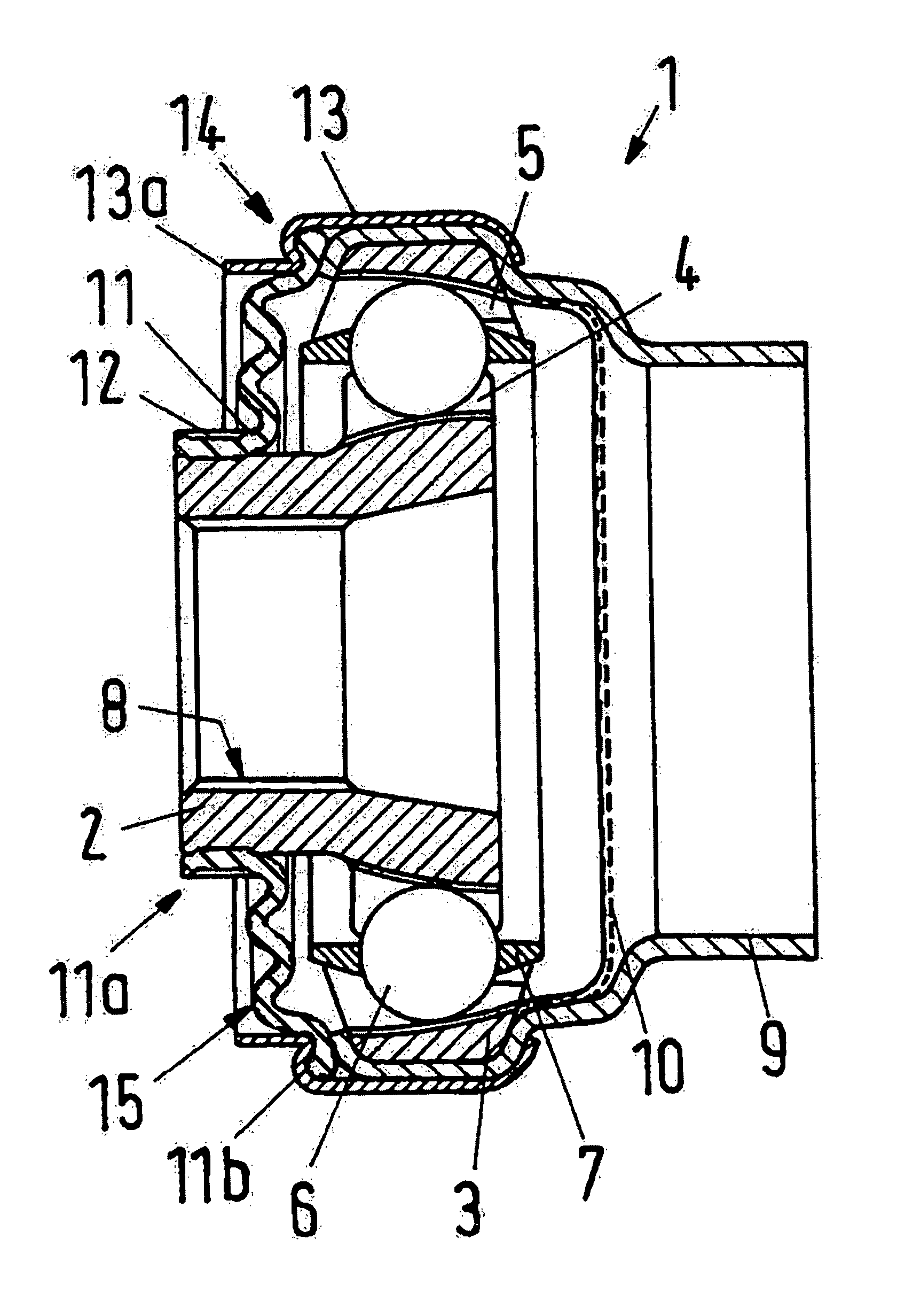
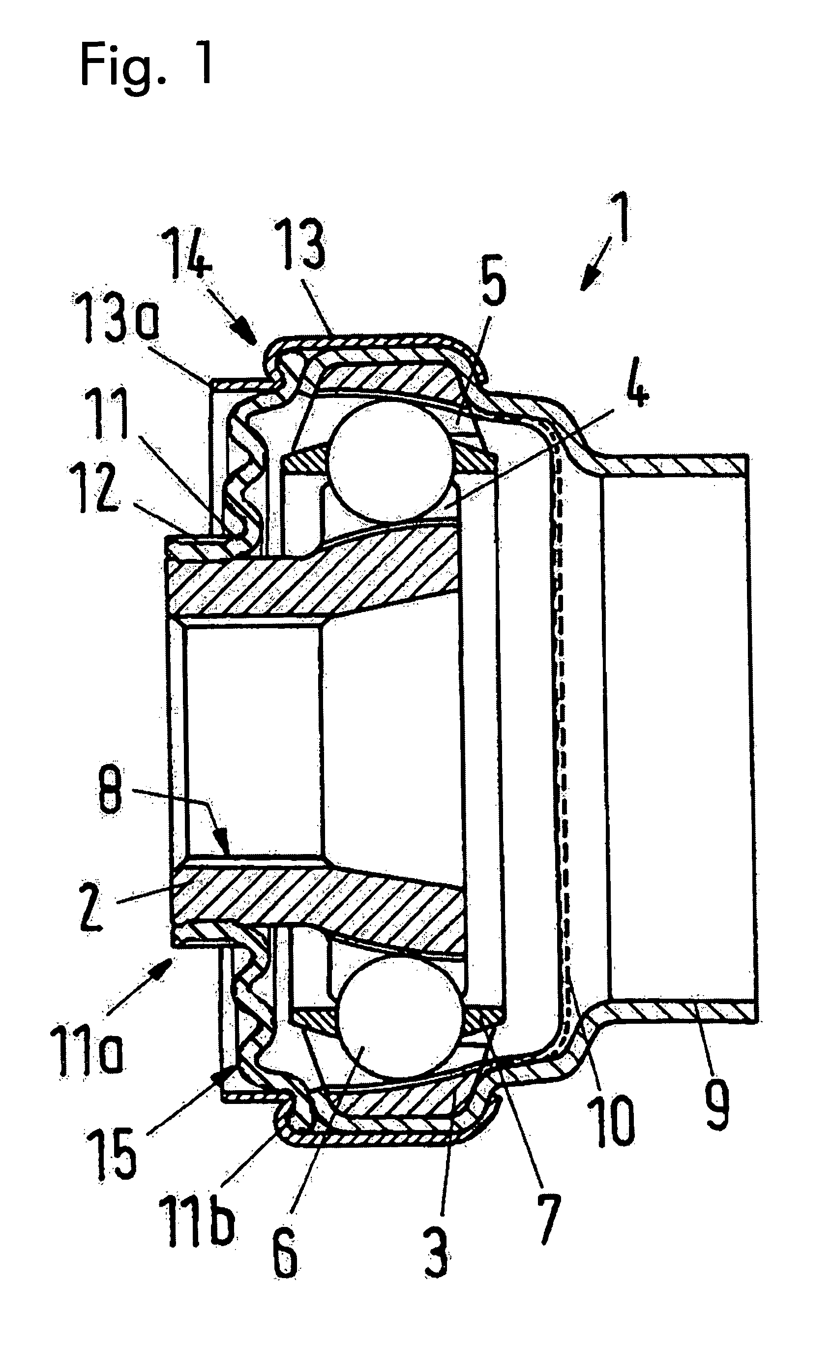
[0010]This task is accomplished, according to the invention, essentially in that the sealing arrangement has a set of bellows, which is articulated onto the outer hub and / or a carrier housing that surrounds the latter, with its radially outer edge, and is attached in stationary manner to the inner hub, with its radially inner edge. Therefore the homokinetic joint, together with the sealing arrangement, forms a sealed and finished unit, which can be set directly onto a shaft with the inner hub. Therefore no additional work is required to attach the sealing arrangement to the shaft during or after
assembly. At the same time, the penetration of contaminants into the region located between the inner hub and the outer hub, containing the balls and the cage, is already prevented, even during transport. The carrier housing that might be provided can be an integral part of the shaft or be connected with it. O-rings or similar additional sealing arrangements, which are generally necessary for a seal in the case of conventional joints, in order to achieve a good sealing effect between the inner and the outer hub, do not have to be provided in the case of the joint sealed according to the invention.
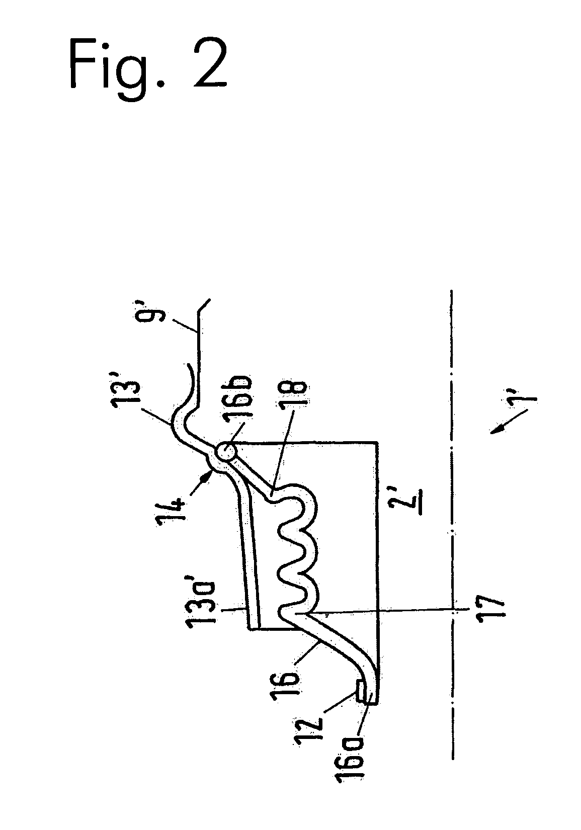
[0014]Preferably, in the case of a displaceable homokinetic joint according to the invention, the peaks of two adjacent pleats are oriented at an angle between approximately 120° and approximately 60° relative to one another. In this way, different functions are assigned to different pleats. Thus, the pleats that are disposed next to one another in the axial direction can balance out an
axial displacement between the inner hub and the outer hub, while one or more pleats disposed next to one another in the radial direction can balance out an incline of the joint.
[0017]Damage to the set of bellows due to high centrifugal forces can be avoided in that the cap has an approximately cylindrical section that extends away from the outer hub, which extends in the axial direction of the inner hub up to the vicinity of the region in which the radially inner edge of the set of bellows is fixed in place on the inner hub. The cylindrical, slightly conical section or stepped region of the cap, which section / region extends away from the outer hub, serves as a contact surface that enters into contact with the set of bellows when the latter inflates due to centrifugal forces at high revolutions. Therefore the set of bellows does not come into contact with sharp-edged or pointed regions of the cap, but rather rests against an essentially
smooth surface, which prevents overly great inflation of and damage to the set of bellows. In the case of a fixed homokinetic joint, this region of the cap, which projects away from the outer hub, is configured to be comparatively short, since the pleats of the set of bellows lie essentially on top of one another in the radial direction. In the case of a displaceable homokinetic joint, however, this region of the cap clearly projects away further from the outer hub.
[0018]The inner edge of the set of bellows can be fixed in place on the inner hub by means of a strap, a tie, a spring ring, or the like, in such a manner that it is held in place in a fixed location on the inner hub during operation. For repair or maintenance work, however, the inner edge of the set of bellows can be released from the inner hub, and is not displaceable on the inner hub only at the stresses that occur during operation. Exit of
lubricant or penetration of
dirt can therefore be avoided. Alternatively to this, it is also possible to fix the inner edge of the set of bellows in place on the inner hub in that a sheet-
metal ring is vulcanized into the edge, and the inner edge of the set of bellows is drawn onto the inner hub with a press fit, i.e. under tension.
[0019]Preferably, the set of bellows consists of rubber or another suitable, for example rubber-like plastic, which has a relatively great rigidity of more than 65
Shore, for example approximately 70
Shore. Because of this rigidity of the material of the set of bellows, the ability of the set of bellows to withstand stress is increased, and the deformations that occur during operation are limited.
[0021]The set of bellows of the joint according to the invention is already well protected against raccoon damage or the like by means of the section that projects away from the cap. Further improved security against such damage can be achieved in that the set of bellows is disposed on a transmission or differential side of the joint, and the outer hub and / or the carrier housing are connected with a shaft. The set of bellows therefore does not face the shaft (for example in the case of installation of the joint into a longitudinal shaft of a vehicle), but rather faces the transmission or differential side of the joint, so that because of the construction space of the transmission, there is only a slight
attack surface available for raccoon damage or the like. Furthermore, because of the connection of the inner hub on which the set of bellows is fixed, on the transmission or differential side, improved centering of the shaft attached to the outer hub or to the carrier housing, respectively, can be achieved.
