
System for supplying an internal combustion engine and method of manufacturing a tank comprised in the system

a technology of internal combustion engine and system, which is applied in the manufacture of tools, mechanical equipment, transportation and packaging, etc., can solve the problems of difficult and expensive manufacture of these known nozzles, the difficulty of producing a hermetically sealed and mechanically strong join between the two tubes, and the additional disadvantage of the nozzl

Inactive Publication Date: 2009-12-03
INERGY AUTO SYST RES SA
View PDF10 Cites 3 Cited by
  • Summary
  • Abstract
  • Description
  • Claims
  • Application Information

AI Technical Summary

Benefits of technology

The invention provides a two-material composite conduit for conveying hot fluids in high-efficiency diesel engines. The conduit is made up of two hollow components that are mechanically attached to each other and in communication with each other. The components are made of different plastics that are impermeable to the fuel and chemically inert with respect to it. The seal between the components is formed by overmolding an elastomeric or other material conventionally used in seal production. The composite conduit is used for conveying hot fluids and is manufacturable using standard plastic molding techniques. The invention aims to provide a sealed composite conduit that is cost-effective, independent of the nature of the polymers used and the fuel type.

Problems solved by technology

The manufacture of these known nozzles is difficult and expensive.
In particular, it is generally difficult to produce a hermetically sealed and mechanically strong join between the two tubes.
These known nozzles thus have the additional disadvantage of lacking flexibility as regards their construction.

Method used


Image

  • System for supplying an internal combustion engine and method of manufacturing a tank comprised in the system
  • System for supplying an internal combustion engine and method of manufacturing a tank comprised in the system

Examples


Embodiment Construction

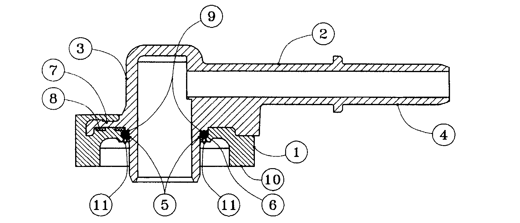
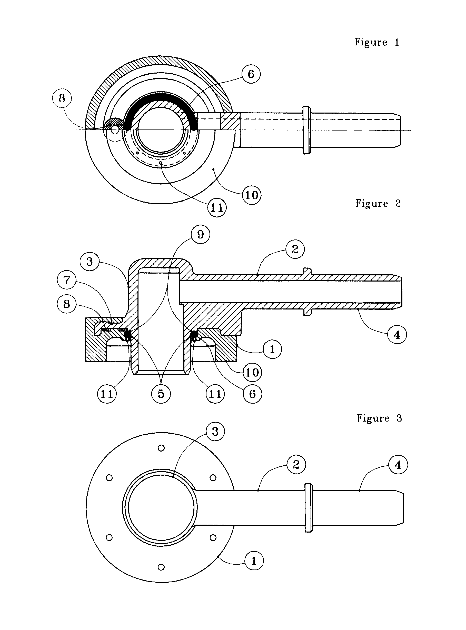
[0044]The composite conduit shown in FIGS. 1 to 3 comprises a cylindrical socket 1 made of high-density polyethylene (HDPE) and a nozzle 2 made of polydodecanolactam (PA12). The nozzle 2 has two straight parts 3 and 4 making approximately a right angle between them. The part 3 of the nozzle 2 passes through a circular opening 5 in the socket 1. The circular opening 5 contains an O-ring seal 6 made of a fluoroelastomer (FPM). A lateral flange 7 of the nozzle 2, inserted into a corresponding notch in the socket 1, constitutes a catching element for making a mechanical connection, rendering the socket 1 inseparable from the nozzle 2.

[0045]A metal disc 8 is also inserted between the socket 1 and the nozzle 2. The socket 1 is intended to be welded, on its front face 10, to an HDPE tank of a vehicle and the part 4 of the nozzle 2 is intended to be connected to a pipe connected to the engine of the vehicle.

[0046]Manufacture of the composite conduit shown in the figures starts with the manu...


PUM

PropertyMeasurementUnit
temperatureaaaaaaaaaa

Abstract

System for supplying an internal combustion engine with a liquid fuel, comprising a tank, a pipe for the circulation of hot fuel between the engine and the tank and at least one sealed composite junction conduit for joining the pipe to the tank. The composite junction conduit comprises at least two hollow components each based on a different plastic, the said components being mechanically attached to each other and in communication with each other and include, between them, an overmoulded seal.

Description

REFERENCE TO PRIOR APPLICATIONS[0001]This application is a Divisional of U.S. application Ser. No. 10 / 573,474, filed Oct. 11, 2006; which is a 371 application of PCT / EP04 / 52314, filed Sep. 24, 2004; and to French patent application 03 11275, filed Sep. 26, 2003, all incorporated herein by reference.FIELD OF THE INVENTION[0002]The invention relates to sealed conduits for the flow of fluids (liquids and / or gases).[0003]It relates more especially to a sealed composite conduit formed by joining together at least two hollow components made of thermoplastic.PRIOR ART[0004]In the automobile industry, great use is made of thermoplastics in internal combustion engine supply systems. The thermoplastics are especially used for the manufacture of fuel tanks and the pipes connecting them to the engine combustion chambers.[0005]Motor car fuel tanks are conventionally produced by extrusion-blow moulding technology. A shell is thus obtained through which openings intended to accommodate functional ...

Claims


Application Information

Patent Timeline
Patent Type & Authority Applications(United States)
IPC IPC(8): B29C45/14B60K15/01
CPCB29C45/14311B29C45/14467B60K15/03177B60K15/01B29C45/14598Y10T137/9029F16L47/26F16L47/20B29C45/14
Inventor THISSELIN, BERTRAND
Owner INERGY AUTO SYST RES SA
Learn More