
Objective lens, optical pickup device, and optical recording/reproducing apparatus

a technology of optical pickup and optical recording, applied in the field of optical recording/reproducing apparatus, can solve the problems of difficult to achieve sufficient optical efficiency in practice, difficult to secure working distance, and difficult to satisfy this demand by promoting a decrease in wavelength, so as to reduce the weight of the lens, and improve the effect of focusing and tracking control

Inactive Publication Date: 2009-11-19
FUJI PHOTO OPTICAL CO LTD
View PDF7 Cites 5 Cited by
  • Summary
  • Abstract
  • Description
  • Claims
  • Application Information

AI Technical Summary

Benefits of technology

[0032]Since each of the objective lenses of [1] and [2] has at least one aspheric surface, it is possible to satisfactorily correct various aberrations. In addition, since each objective lens is formed of a single lens, it is possible to contribute to reduction in weight of lens. As a result, it is possible to reduce a weight of lens, which enables to drive the lens at a higher speed in focusing and tracking controls.
[0033]Furthermore, since the objective lenses of [1] and [2] satisfy the conditional expression (1), a lens material having a low refractive index can be used, and a specific gravity of a lens material, which has a tendency to increase in specific gravity in accordance with an increase in refractive index, can be set small. Therefore, it is possible to achieve reduction in weight of the lens. Thereby, it is possible to drive the lens at a high speed in the focusing and tracking controls.
[0034]Further, since the objective lens of [1] and [2] satisfy the conditional expression (2), it is possible to prevent an excessive increase in curvature of the optical recording medium side surface. Thereby, it is possible to reduce spherical aberration caused by the optical recording medium side surface. On the other hand, it is also possible to prevent an excessive increase in curvature of the light source side surface. As a result, it is possible to increase a working distance of the objective lens.
[0035]In addition, since the objective lens of [1] satisfies the conditional expression (3), it is possible to obtain favorable off-axis characteristics by satisfying the lower limit range thereof. On the other hand, by satisfying the upper limit range thereof, it is possible to decrease a weight and a volume of the objective lens. As a result, it is possible to drive the objective lens at a high speed during control.
[0036]Further, since the objective lens of [2] satisfies the conditional expression (4), it is possible to decrease a weight and a volume of the objective lens by satisfying the lower limit range thereof. Accordingly, it is possible to drive the objective lens at a high speed during control. On the other hand, by satisfying the upper limit range, it is possible to increase a working distance of the objective lens.
[0037]According to the above configurations, it is possible to provide an optical pickup device having the objective lens, which has the above-mentioned advantages, and the optical recording / reproducing apparatus.

Problems solved by technology

However, in future, as might be expected, an increase in density will be demanded more and more, but it may be hard to satisfy this demand by promoting a decrease in wavelength.
This is because optical transmittance of lens materials is rapidly reduced in the range of a wavelength less than 350 nm and thus, it is hard to obtain sufficient optical efficiency in practice.
Meanwhile, in the high-NA objective lens for an optical pickup device, it is difficult to secure a working distance (WD) that can prevent collision between the lens and an optical recording medium while maintaining compactness of the lens system.
However, in the objective lens described in Japanese patent No. 3712628, a refractive index of the lens component material is set high, and thus a weight of lens becomes large.
This causes a problem in that it is difficult to drive a lens at a high speed in focusing and tracking controls since the weight of the lens described in Japanese patent No. 3712628 becomes large in any cases.

Method used


Image

  • Objective lens, optical pickup device, and optical recording/reproducing apparatus
  • Objective lens, optical pickup device, and optical recording/reproducing apparatus
  • Objective lens, optical pickup device, and optical recording/reproducing apparatus

Examples


example 1

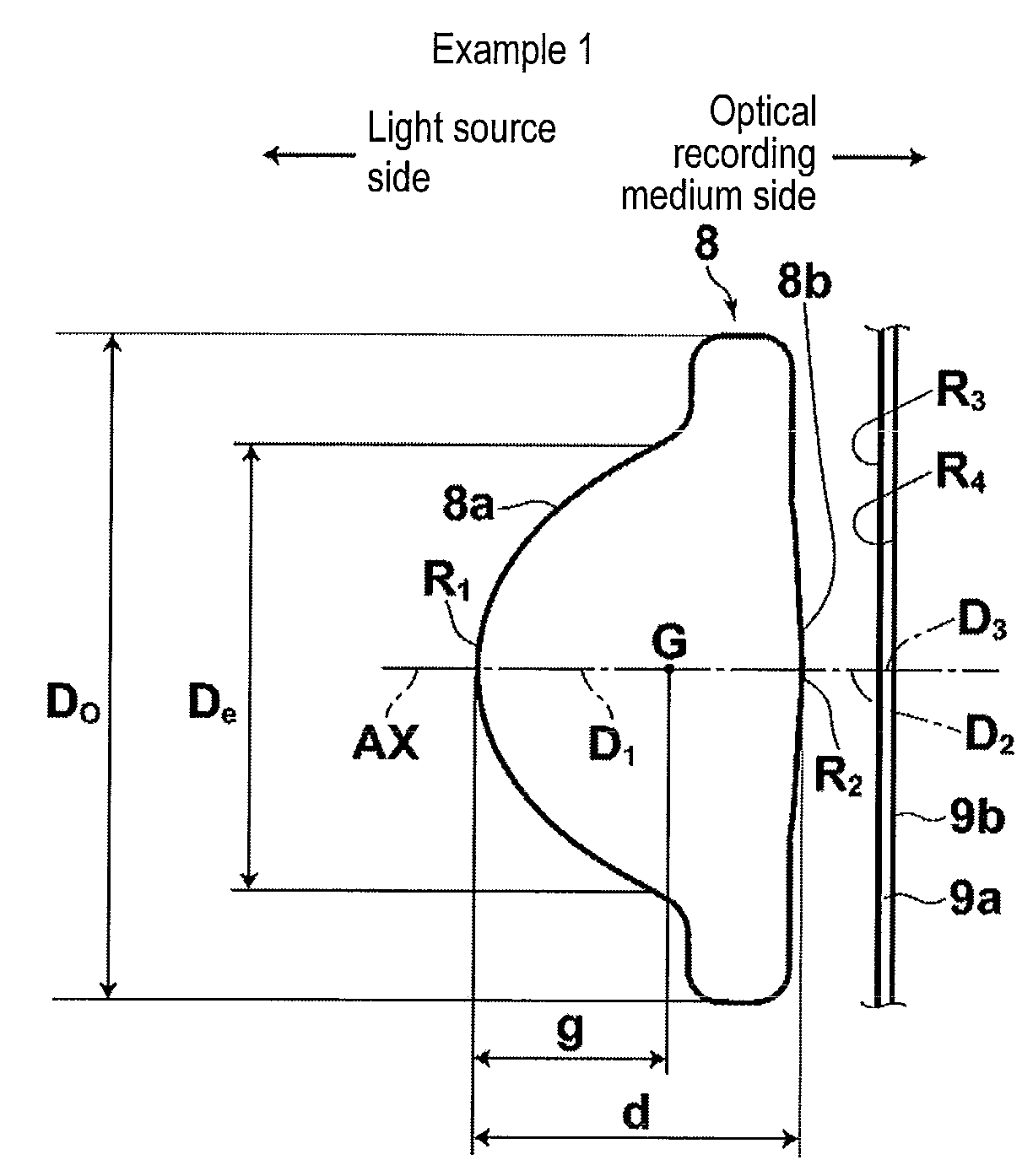
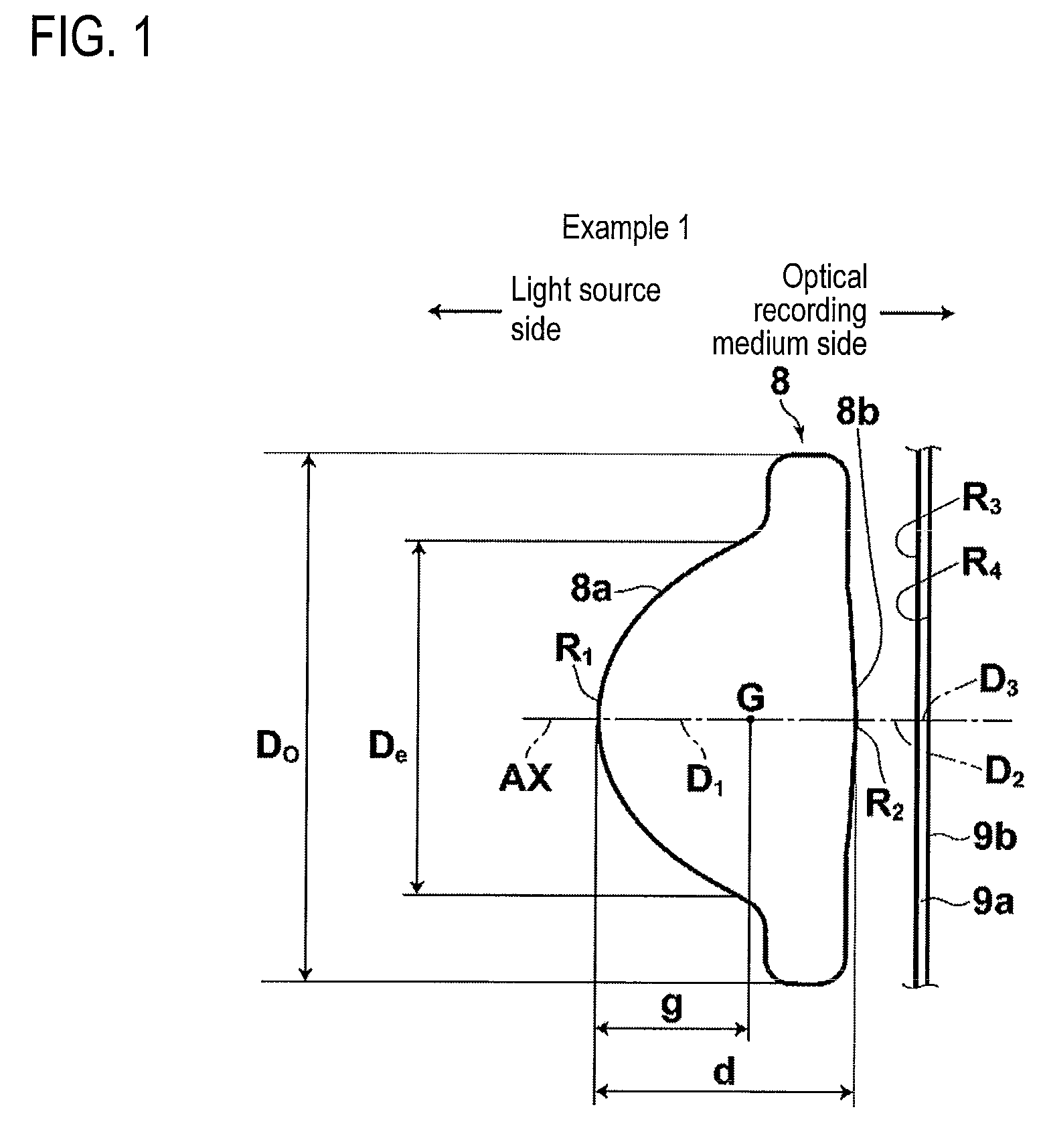
[0108]The objective lens 8 according to Example 1 is formed of a single lens made of glass. As shown in FIG. 1, the light source side surface 8a and the optical recording medium side surface 8b are convex surfaces near the optical axis, and the light source side surface 8a is the convex surface having a larger curvature than the optical recording medium side surface 8b. Furthermore, both the surfaces of the objective lens 8 according to this example are aspheric surfaces each of which is rotationally symmetric.

[0109]In the upper part of the following Table 1, surface numbers are assigned so as to sequentially increase as it gets closer to the optical recording medium side from the light source side when the light source side surface is numbered as 1. The upper part thereof also shows the following items as lens data of the objective lens 8 according to Example 1: radiuses of curvature R (mm) of surfaces; on-axis surface spacings D (mm); and refractive indices N at a wavelength of th...

example 2

[0114]The objective lens 8 according to Example 2 is formed of a single lens made of glass. As shown in FIG. 2, the light source side surface 8a and the optical recording medium side surface 8b are convex surfaces near the optical axis, and the light source side surface 8a is the convex surface having a larger curvature than the optical recording medium side surface 8b. Furthermore, both the surfaces of the objective lens 8 according to this example are aspheric surfaces each of which is rotationally symmetric.

[0115]As for data according to Example 2, the upper part of the following Table 2 shows lens data, the middle part thereof shows aspheric surface data, and the lower part thereof shows various data.

TABLE 2Example 2Radius ofcurvature RSurface spacingRefractiveSurface(mm)D (mm)index N1Aspheric1.4471.6052Aspheric0.3371.0003∞0.10001.6194∞1st surface2nd surfaceC1.211757025−0.569673325K2.231072347E−019.067227885E−01A46.679499460E−021.623953466E+00A67.115742222E−02−6.252104914E+00A8−...

example 3

[0118]The objective lens 8 according to Example 3 is formed of a single lens made of plastic. As shown in FIG. 3, the light source side surface 8a and the optical recording medium side surface 8b are convex surfaces near the optical axis, and the light source side surface 8a is the convex surface having a larger curvature than the optical recording medium side surface 8b. Furthermore, both the surfaces of the objective lens 8 according to this example are aspheric surfaces each of which is rotationally symmetric. Furthermore, the optical recording medium side surface of the objective lens 8 of this example is formed in a convex shape near the optical axis and is formed in a concave shape at a predetermined position distant from the optical axis AX.

[0119]As for data according to Example 3, the upper part of the following Table 3 shows lens data, the middle part thereof shows aspheric surface data, and the lower part thereof shows various data.

TABLE 3Example 3Radius ofcurvature RSurfa...


PUM

PropertyMeasurementUnit
massaaaaaaaaaa
wavelengthaaaaaaaaaa

Abstract

An objective lens for converging light emitted from a light source on an optical recording medium to record and reproduce information consists of a single lens having at least one aspheric surface. The following conditional expressions (1) to (3) are satisfied:N≦1.75  (1)0.5<f / f1<0.6  (2)0.8<d / (NA·De)<1.0  (3)whereN denotes a refractive index,f denotes a focal length (mm),f1 denotes a focal length (mm) of a light source side surface,d denotes a thickness (mm) on an optical axis,NA denotes a numerical aperture on an optical recording medium side, andDe denotes an effective aperture (mm) of the light source side surface.

Description

CROSS-REFERENCE TO RELATED APPLICATIONS[0001]This application is based upon and claims the benefit of priority from the Japanese Patent Application No. 2008-129205 filed on May 16, 2008; the entire contents of which are incorporated herein by reference.BACKGROUND OF THE INVENTION[0002]1. Technical Field[0003]The invention relates to an objective lens, an optical pickup device, and an optical recording / reproducing apparatus. Specifically, the invention relates to an objective lens for use in an optical pickup apparatus for converging light emitted from a light source onto an optical recording medium to perform at least one of operations of recording and reproducing information, an optical pickup device having the objective lens, and an optical recording / reproducing apparatus equipped with the optical pickup device.[0004]2. Description of the Related Art[0005]Generally, various optical recording media such as DVD (digital versatile disk) and CD (compact disk) have been used in order t...

Claims


Application Information

Patent Timeline
Patent Type & Authority Applications(United States)
IPC IPC(8): G11B7/00
CPCG11B7/1374G02B3/04G02B13/18
Inventor KATSUMA, TOSHIAKIMORI, MASAOORI, TETSUYAKITAHARA, YU
Owner FUJI PHOTO OPTICAL CO LTD
Learn More