
Method and device for evaluating shafting alignment of ship

a technology for shafting alignment and engine, which is applied in the direction of vessel construction, process and machine control, instruments, etc., can solve the problem of inability to evaluate whether the estimated bearing position is appropriate or not, and achieve the effect of easy evaluation and quick evaluation

Inactive Publication Date: 2009-10-29
HITACHI ZOSEN CORP
View PDF13 Cites 12 Cited by
  • Summary
  • Abstract
  • Description
  • Claims
  • Application Information

AI Technical Summary

Benefits of technology

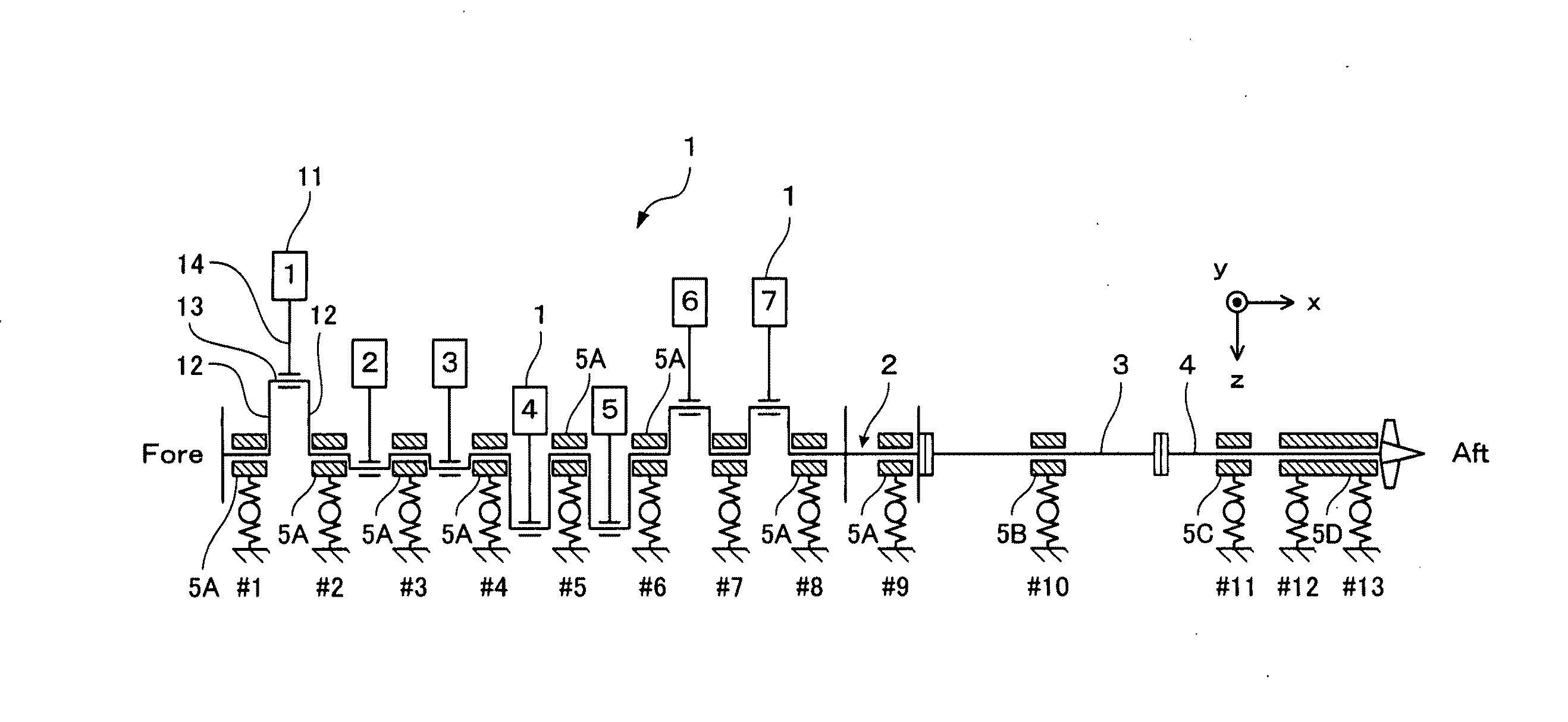
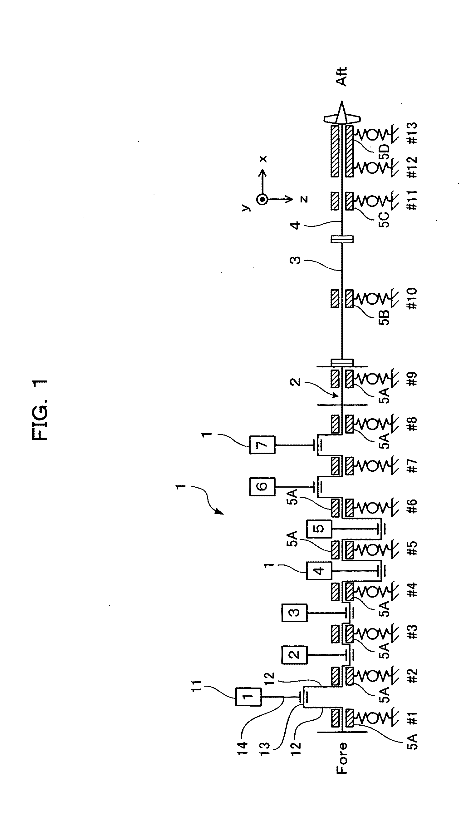
The present invention provides a method and device for evaluating the alignment of drive shafting in a ship. The method involves calculating the displacement of a predetermined portion of the drive shafting using a transfer matrix method based on the inclinations of the crankshaft and intermediate shaft, and evaluating the alignment by comparing the calculated displacement with a preset evaluation condition. The device includes a data input unit, bearing position calculating unit, shafting displacement calculating unit, evaluation index calculating unit, and evaluating unit. The invention allows for easy evaluation of the alignment of drive shafting regardless of whether the ship is in service or new build.

Problems solved by technology

Unfortunately, according to the method for detecting the position of drive shafting described above, while the current installation position of a bearing can be accurately estimated, an evaluation as to whether the estimated bearing position is appropriate or not cannot be made.

Method used


Image

  • Method and device for evaluating shafting alignment of ship
  • Method and device for evaluating shafting alignment of ship
  • Method and device for evaluating shafting alignment of ship

Examples


first embodiment

[0084]A method and a device for evaluating the shafting alignment of a ship according to a first embodiment of the present invention will now be described.

[0085]First, an outline of a shafting alignment evaluating method according to the present invention will be presented.

[0086]In simple terms, the present invention is achieved so that an evaluation of shafting alignment is performed based on the inclination of a crankshaft (also referred to as an engine shaft) and the inclination of an intermediate shaft of an engine of a ship, and, furthermore, such an evaluation can be readily performed using an evaluation map.

[0087]The evaluation map is a map in a two-dimensional plane whose coordinate axes are the inclination of the crankshaft and the inclination of the intermediate shaft and which is an easily understandable graphic representation (visualization) of which evaluation level a crank deflection of the engine calculated in response to each inclination and bearing loads acting on b...

second embodiment

[0266]A device for evaluating the shafting alignment of a ship according to a second embodiment of the present invention will now be described.

[0267]While an evaluating device is configured by a single computer system in the first embodiment described above, in the present second embodiment, a client / server system is used in which a portion of functions of a data input unit and an output unit is provided at a client that is a terminal and other portions thereof are provided at a server device connected to the client via a network.

[0268]A case of a client / server system will now be described.

[0269]Generally, with a service in which a user-side personal computer (PC) is used as a client (terminal) and a server device is connected to the client via a network such as the Internet, a method is widely used in which information transmitted over the Internet (World Wide Web) is inputted using a client-side browsing software (browser) and transmitted to the server device, and output from the ...


PUM


Abstract

An evaluation map showing the allowable ranges (A) of the crank deflection and bearing loads determined according to the inclination of the crankshaft of an engine and the intermediate shaft is prepared beforehand. When the engine is installed in a ship, the inclination of the shafts within the allowable ranges can be easily known. While the ship is in service, the shafting alignment of the ship can be evaluated by merely measuring the inclination of the crankshaft and the intermediate shaft.

Description

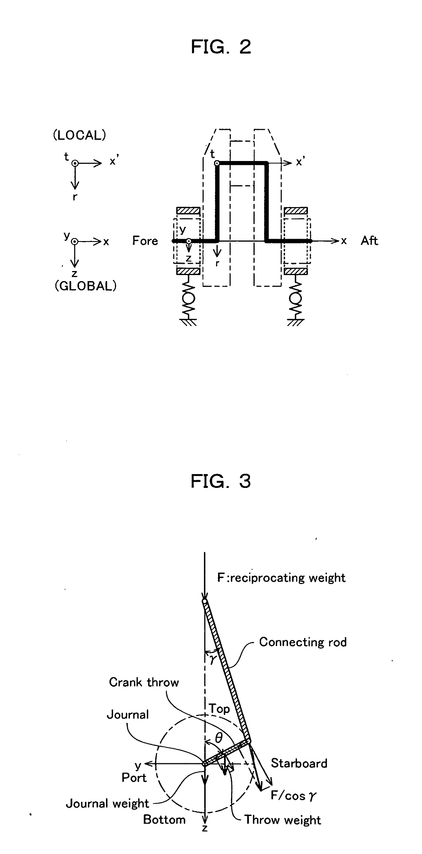
TECHNICAL FIELD[0001]The present invention relates to a method and device for evaluating shafting alignment in a marine engine.BACKGROUND ART[0002]When installing an engine that is a main engine and a propeller shaft in a ship, it is necessary to accurately align shaft-center positions of drive shafting made up of a crankshaft of the engine, an intermediate shaft and a propeller shaft or, in other words, perform shafting alignment.[0003]As a method capable of accurately performing such shafting alignment, the present inventors have proposed a method for detecting the position of drive shafting (for example, refer to Japanese Patent Laid-Open No. 2003-19997 (also referred to herein as Patent Document 1)).[0004]The aforementioned position detecting method will now be briefly described. First, a crankshaft is modeled and respective bearing positions are presupposed. The state quantity (displacement and acting force) of the fore bearing of the crankshaft is transferred to an aft-side us...

Claims


Application Information

Patent Timeline
Patent Type & Authority Applications(United States)
IPC IPC(8): G06F19/00
CPCB63B9/00G01M17/00B63H23/34B63B9/003B63B71/10B63B71/00G01B21/24G01B21/22
Inventor SUGIMOTO, IWAO
Owner HITACHI ZOSEN CORP
Learn More