
Methods of producing microparticles

Inactive Publication Date: 2009-10-29
MUCOVAX
View PDF2 Cites 8 Cited by
  • Summary
  • Abstract
  • Description
  • Claims
  • Application Information

AI Technical Summary

Benefits of technology

[0016]Microfluidising instruments (microfluidisers), have previously been used in the manufacture of paints and inks. However, Applicants have now surprisingly found that microfluidising instruments may also be used to produce CMP of a phagocytosable size, and thus CMP produced using a microfluidising instrument are appropriate for use as a pharmaceutical and for formulation in pharmaceutical compositions. In particular, Applicants have found that advantages of using a microfluidising instrument to produce CMP include the ability to handle large volumes and the ease of scale up for industrial manufacturing needs; GMP protocols have been developed; it produces a homogenous product with greater control over particle size than other methods; and it gives a greater yield of CMP than other methods.
[0018]Essentially, microfluidising instruments suitable for use in the invention reduce particle size by propelling a product (e.g. a suspension) through geometrically fixed micro channels at high pressure, e.g. 20,000 to 30,000 psi, and high velocity, e.g. in excess of 500 ms−1. This provides an extremely focused interaction zone. As the product passes through the microchannels, forces produced by the high pressure act upon the product to reduce the size of particles in the product, including shear forces, through deformation of the product stream occurring from contact with the walls of the microchannels; impact forces, through collisions occurring when the high velocity product stream impinges upon itself; and cavitation forces, through formation and collapse of vapour cavities within the product stream.
[0024](b) passing the suspension through a microfluidising instrument to reduce the average diameter of the particles in the collection of particles to the desired average diameter;
[0041]Increasing the operating pressure of the microfluidising instrument, i.e. the pressure at which the suspension is passed through the microfluidising instrument, and / or adjusting the size e.g. diameter, and / or geometry of the microchannels may affect, e.g. reduce, the number of times the suspension must be passed through the microfluidising instrument to reduce the average diameter of the particles in the collection to the desired average diameter. Applicants have found that the use of an operating pressure and a size and geometry of microchannels such that the suspension is passed through the microfluidising instrument at least 7 times or more, more preferably at least 9 times or more, is optimal for minimising overheating and / or blockage of the microfluidising instrument. The person skilled in the art is able to select such an appropriate operating pressure and size and geometry of the microchannels.
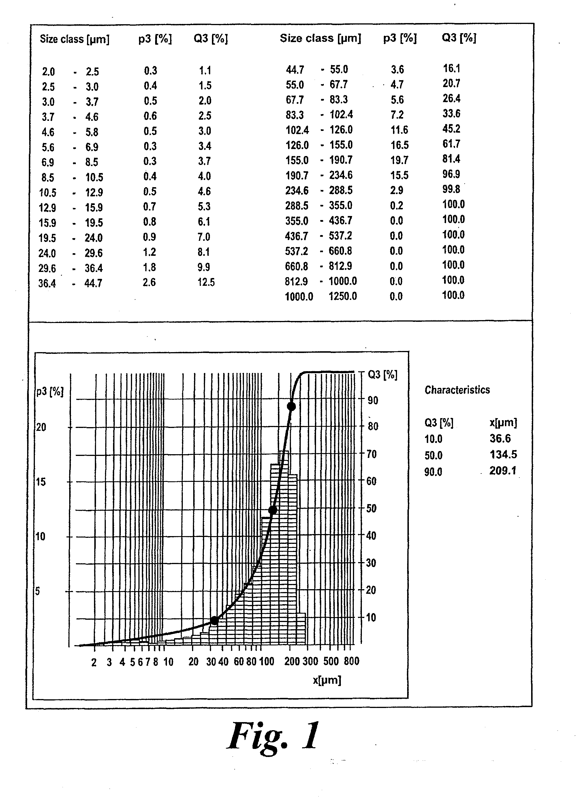
[0043]The method may also comprise sieving the collection of particles prior to passing the particles through the microfluidising instrument. A collection of particles may include particles that are large enough to block the microchannels, e.g. particles having a diameter of 50 μm or larger, and thus sieving the collection of particles prior to passing the particles though the microfluidising instrument would reduce the possibility of particles blocking the microchannels. Sieving also allows the starting size of the particles to be reduced. This can be advantageous, as Applicants have found that the yield of microparticles increases as the size of the starting particles decreases. Thus, preferably the method comprises sieving the collection of particles prior to making the suspension and / or passing the collection of particles through the microfluidising instrument. Preferably the sieve has a pore size of 200 μm or less, 150 μm or less, or 100 μm or less. Most preferably the sieve has a pore size of 126 μm.
[0058]Applicants also compared the therapeutic efficacy of CMP produced by dry powder ball milling with CMP produced using a microfluidising instrument. However, Applicants found that the CMP produced using a microfluidising instrument was more effective than CMP produced by dry powder ball milling in treating asthma in mice. In particular, Applicants found that the CMP produced using a microfluidising instrument resulted in greater reduction in alveolar eosinophils, indicating that treatment reduced the level of asthma, and in a greater reduction of cellular inflammation in the lungs. In addition, Applicants have also shown that CMP produced using a microfluidising instrument provides protection against viral infection.

Problems solved by technology

However, when Applicants investigated air-jet milling as a method for the production of CMP Applicants found that after three passes the average particle size was still greater than 100 μm, indicating that this method is completely ineffective for producing CMP.
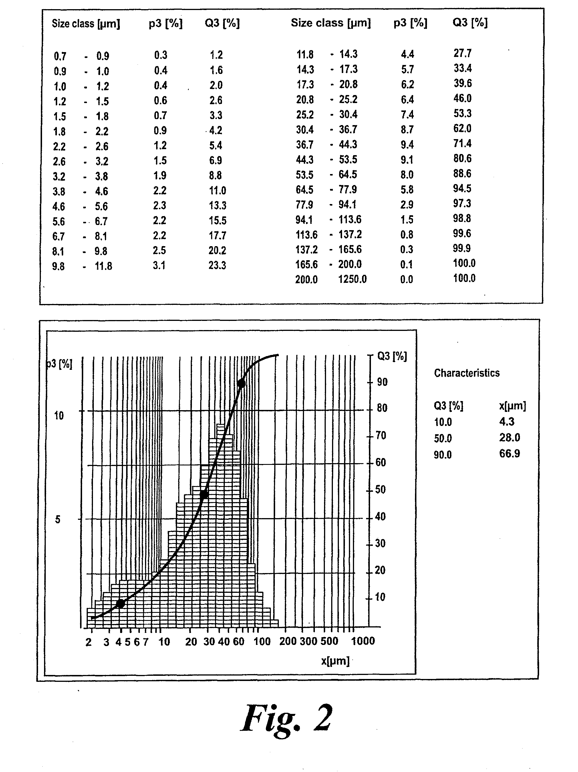
Applicants also found that dry powder ball milling is an unsatisfactory method for producing CMP because the time required to produce particles approaching a phagocytable size was excessive, i.e. of the order of days, and even then the average particle size was around 50 μm rather than the more desirable 10 μm.
In addition, the excessive milling time is likely to produce metal contamination from wear to the metal balls.

Method used


Image

  • Methods of producing microparticles
  • Methods of producing microparticles
  • Methods of producing microparticles

Examples


examples

1. Evaluation of Methods for the Production of CMP

[0108]Various methods of producing particles were evaluated as methods for producing CMP.

[0109]Particle size and particle size distribution was determined using an AccuSizer 780 Optical Particle Sizer, which is manufactured by Particle Sizing Systems.

[0110]The typical size distribution of standard milled chitin powder obtained from the manufacturer is shown in FIG. 1.

Production of CMP by Dry Ball Milling

[0111]Dry powder ball milling was evaluated as a method for producing CMP. Milling was performed by Heppe GmbH using a bench top ball mill. The final particle size distribution is shown in FIG. 2. However, this method was found to be unsatisfactory for several reasons:

1. The time required for ball milling was excessive and in the order of days of continuous milling. This is not practical for industrial scale-up.

2. The extended milling times is likely to produce heavy metal contamination from ware to the metal balls used in the mill.

3....


PUM

PropertyMeasurementUnit
Pressureaaaaaaaaaa
Diameteraaaaaaaaaa
Lengthaaaaaaaaaa

Abstract

Methods of producing microparticles, and especially chitin microparticles (CMP), are disclosed that involve reducing the size of (larger) particles using a (high shear) microfluidising instrument.

Description

INCORPORATION BY REFERENCE[0001]This application is a continuation-in-part application of international patent application Serial No. PCT / GB2007 / 004129 filed Oct. 29, 2007, which published as PCT Publication No. WO 2008 / 053192 on May 8, 2008, which claims benefit of U.S. provisional patent application Ser. No. 60 / 855,185 filed Oct. 30, 2006.[0002]The foregoing applications, and all documents cited therein or during their prosecution (“appln cited documents”) and all documents cited or referenced in the appln cited documents, and all documents cited or referenced herein (“herein cited documents”), and all documents cited or referenced in herein cited documents, together with any manufacturer's instructions, descriptions, product specifications, and product sheets for any products mentioned herein or in any document incorporated by reference herein, are hereby incorporated herein by reference, and may be employed in the practice of the invention.FIELD OF THE INVENTION[0003]The present...

Claims


Application Information

Patent Timeline
IPC IPC(8): A61K31/722A61P37/08
CPCA61K9/0043A61K9/1652A61K2039/55583A61K39/39A61K2039/544A61K9/1694A61P11/00A61P11/02A61P11/06A61P17/00A61P17/04A61P27/16A61P31/00A61P31/10A61P31/12A61P31/16A61P31/20A61P35/00A61P37/00A61P37/02A61P37/04A61P37/06A61P37/08A61P43/00
Inventor STRONG, PETER
Owner MUCOVAX
Learn More