Fixing device and image forming apparatus including the same
a technology of fixing device and fixing roller, which is applied in the direction of electrographic process apparatus, ohmic resistance heating, instruments, etc., can solve the problems of increasing the temperature of the fixing roller cannot stay close to the fixing temperature, and the thermal conductivity of the elastic layer of the elastic roller is extremely low, so as to suppress the abnormal temperature rise and increase the operating speed. , the effect of simple configuration
- Summary
- Abstract
- Description
- Claims
- Application Information
AI Technical Summary
Benefits of technology
Problems solved by technology
Method used
Image

Examples
first embodiment
Fixing Device
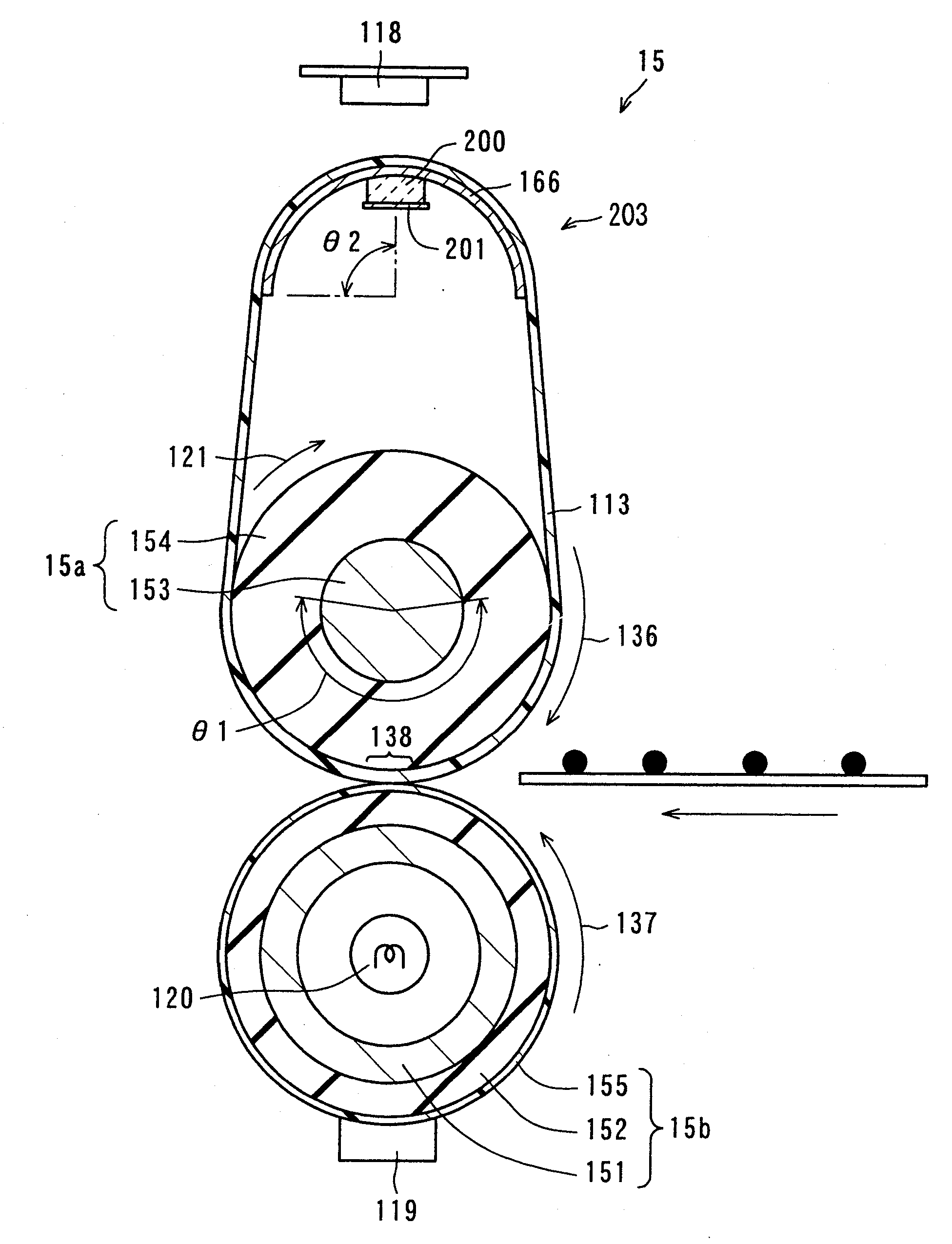
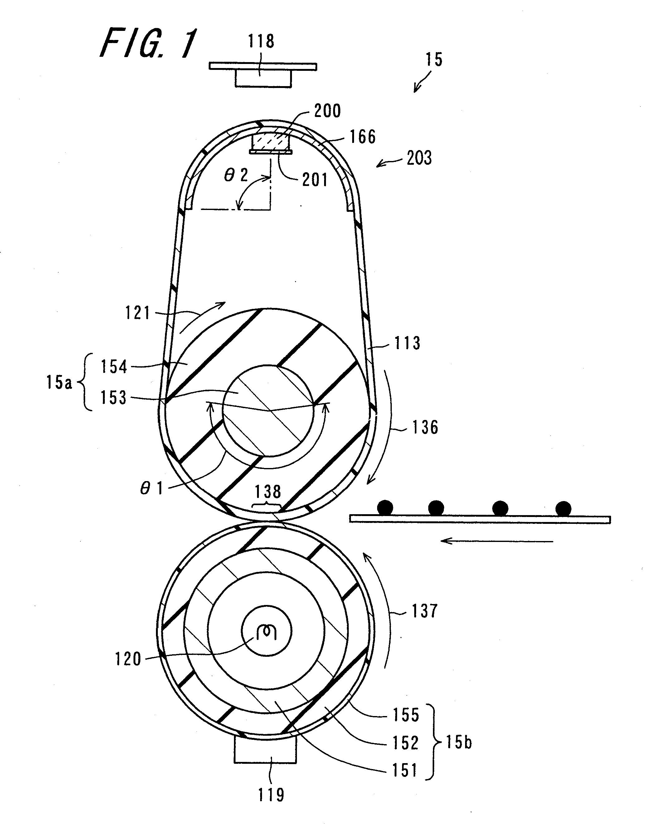
[0065]FIG. 1 is a sectional view schematically showing the configuration of a fixing device 15 according to the first embodiment of the invention. As shown in FIG. 1, the fixing device 15 includes a fixing roller 15a, a pressure roller 15b, an endless fixing belt 113, a planar heating member 203 around which the fixing belt 113 is supported and which serves to heat, a heater lamp 120 which is a heat source for heating the pressure roller 15b, and first and second thermistors 118 and 119 which are temperature sensors constituting a temperature detection section for detecting the temperatures of the fixing belt 113, the pressure roller 15b, etc.
[0066]The fixing device 15 fixes an unfixed toner image formed on a front surface of a recording medium, onto the recording medium under heat and pressure. The fixation is performed under heat and pressure in a fixing nip region 138 where the fixing belt 113 and the pressure roller 15b are brought into pressure-contact with each ot...
second embodiment
Fixing Device
[0099]Next, a fixing device 215 according to a second embodiment of the invention will be described. The fixing device 215 of this embodiment is quite the same as the fixing device 15 of the first embodiment, except the configuration of a planar heating member 204. Therefore, the description of the configuration of the fixing device 215 except the planar heating member 204 will be omitted. The configuration of the planar heating member 204 of this embodiment will be described with reference to FIG. 4. FIG. 4 is a sectional view of a periphery of the planar heating member 204 provided in the fixing device 215 of this embodiment.
[0100]As shown in FIG. 4, the planar heating member 204 of this embodiment differs from the planar heating member 203 of the first embodiment, only in the shape of a high-thermal-conductive heat diffusion member 266b which is included in the planar heating member 204 of this embodiment. The high-thermal-conductive heat diffusion member 266b has su...
examples
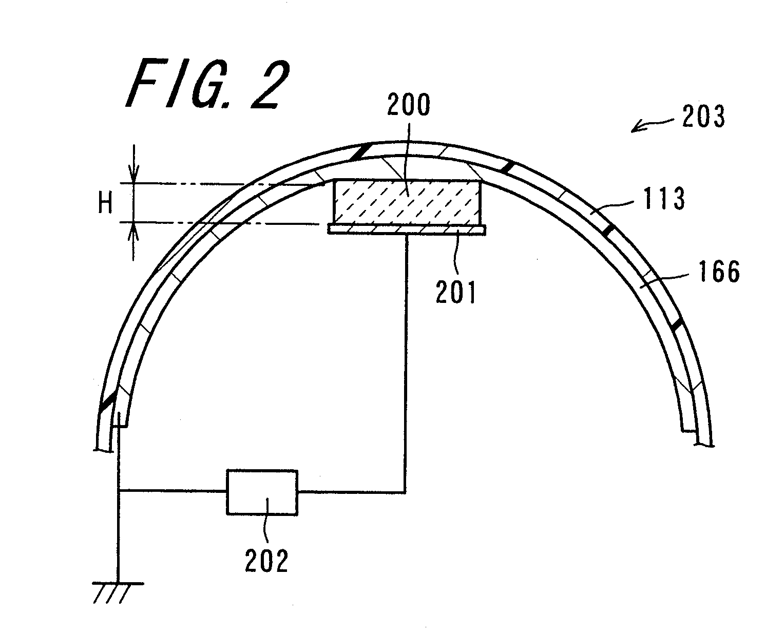
[0127]There will now be described the heat diffusion effects of the high-thermal-conductive heat diffusion member based on a heat conduction simulation. Heat conduction simulation conditions are the three of (1) a position at which the PTC ceramic heat generating element is attached to the heat diffusion member, (2) the property of the heat diffusion member, and (3) the sectional shape of the heat diffusion member. Using these conditions as parameters, the thermal energy conducted from the planar heating member to the fixing belt was found, thereby to estimate the heat diffusion performance and the heat conduction performance of the high-thermal-conductive heat diffusion member.
[0128](1) Attachment Position of PTC Ceramic Heat Generating Element
[0129]Using the fixing device of the first embodiment, fixation operations were respectively performed in three cases where the attachment angles of the PTC ceramic heat generating elements were θ2=25°, 90° and 155°, and the heating performan...
PUM
 Abstract
Description
Claims
Application Information
 - R&D
- Intellectual Property
- Life Sciences
- Materials
- Tech Scout
- Unparalleled Data Quality
- Higher Quality Content
- 60% Fewer Hallucinations
Browse by: Latest US Patents, China's latest patents, Technical Efficacy Thesaurus, Application Domain, Technology Topic, Popular Technical Reports.
© 2025 PatSnap. All rights reserved.Legal|Privacy policy|Modern Slavery Act Transparency Statement|Sitemap|About US| Contact US: help@patsnap.com