
Solid-state image capturing device, manufacturing method of the solid-state image capturing device, and electronic information device

a solid-state image and image capturing technology, applied in the direction of still video cameras, color televisions, television systems, etc., can solve the problems of increasing manufacturing costs, reducing the efficiency of light focusing, so as to improve the light focusing efficiency and high quality , the effect of high performan

Active Publication Date: 2009-10-15
SMARTSENS TECH (SHANGHAI) CO LTD
View PDF6 Cites 42 Cited by
  • Summary
  • Abstract
  • Description
  • Claims
  • Application Information

AI Technical Summary

Benefits of technology

[0033](2) As indicated in Reference 4 with regard to the refractive index variable microlens and the inner-layer lens formed by layering a refractive index variable material layer formed of an electro-optics ceramics, such as PLZT and LiNbO3 by the spattering method, it is necessary to form transparent electrodes on the top and bottom of the lens and process the wiring for applying a voltage, which results in a problem of complicating the steps and increasing the manufacturing cost. In addition, when the refractive index variable microlens is installed in the solid-state image capturing device, the range in which the refractive index can be changed is about 2.2 to 2.6 under the condition where the translucency is maintained by the voltage application and a mechanical strain does not occur. Further, although the refractive index of the overall microlens and inner-layer lens is changed by the voltage application, the improvement on the light focusing rate cannot be expected with respect to the increase on the aspect ratio due to the reduction of the pixel size described in the above (1). Therefore, instead of changing the refractive index of the lens every time in accordance with the diaphragm of the camera lens, it is more advantageous, in terms of the performance and the cost, to design the thickness, shape and refractive index of a microlens and inner-layer lens for each use of the camera and to manufacture a microlens and inner-layer lens suitable for such use.
[0034]The present invention is intended to solve the conventional problems described above. The objective of the present invention is to provide a solid-state image capturing device that is capable of improving the light focusing rate of the microlens and inner-layer lens in response to the required performance of the device, a method for manufacturing the solid-state image capturing device, and an electronic information device, such as a camera-equipped cell phone device, having the solid-state image capturing device as an image input device in an image capturing section thereof.
[0050]An electronic information device according to the present invention includes the solid-state image capturing device according to the present invention as an image input device in an image capturing section, thereby achieving the objective described above.
[0052]In the present invention, a lens is provided at a location on a first transparent film corresponding to the photoelectric conversion section. This lens is formed a second transparent film layered in such a manner to change the refractive index successively or incrementally inside the film, and at least one of the top or bottom surfaces of the second transparent film is formed in a convex shape. As a result, the refractive index of the lens is changed either successively or incrementally inside the film, and a light is focused gradually from a higher position, thereby improving the light focusing efficiency reaching the photoelectric conversion section. Therefore, it becomes possible to achieve a solid-state image capturing device comprising an inner-layer lens and a microlens thereon, which have a high quality and high performance having a desired optical characteristic in which the refractive index is designed in accordance with a required performance of the device.
[0053]According to the present invention with the structure described above, in the field of a solid-state image capturing device including, for example, an inner-layer lens and a microlens thereon as the lenses, a first transparent film is formed on a semiconductor substrate (or semiconductor area) having at least a photoelectric conversion section formed therein, a second transparent film having a refractive index different from that of the first transparent film is formed by changing its refractive index successively or incrementally inside the film, and a convex shape is formed on at least one of the top and bottom surfaces of the second transparent film at a location on the first transparent film corresponding to the photoelectric conversion section. As a result, it becomes possible to obtain a solid-state image capturing device comprising an inner-layer lens and a microlens thereon, which have a high quality and high performance having a desired optical characteristic in which the refractive index is designed in accordance with a required performance of the device.

Problems solved by technology

(2) As indicated in Reference 4 with regard to the refractive index variable microlens and the inner-layer lens formed by layering a refractive index variable material layer formed of an electro-optics ceramics, such as PLZT and LiNbO3 by the spattering method, it is necessary to form transparent electrodes on the top and bottom of the lens and process the wiring for applying a voltage, which results in a problem of complicating the steps and increasing the manufacturing cost.
Further, although the refractive index of the overall microlens and inner-layer lens is changed by the voltage application, the improvement on the light focusing rate cannot be expected with respect to the increase on the aspect ratio due to the reduction of the pixel size described in the above (1).

Method used


Image

  • Solid-state image capturing device, manufacturing method of the solid-state image capturing device, and electronic information device
  • Solid-state image capturing device, manufacturing method of the solid-state image capturing device, and electronic information device
  • Solid-state image capturing device, manufacturing method of the solid-state image capturing device, and electronic information device

Examples


embodiment 1

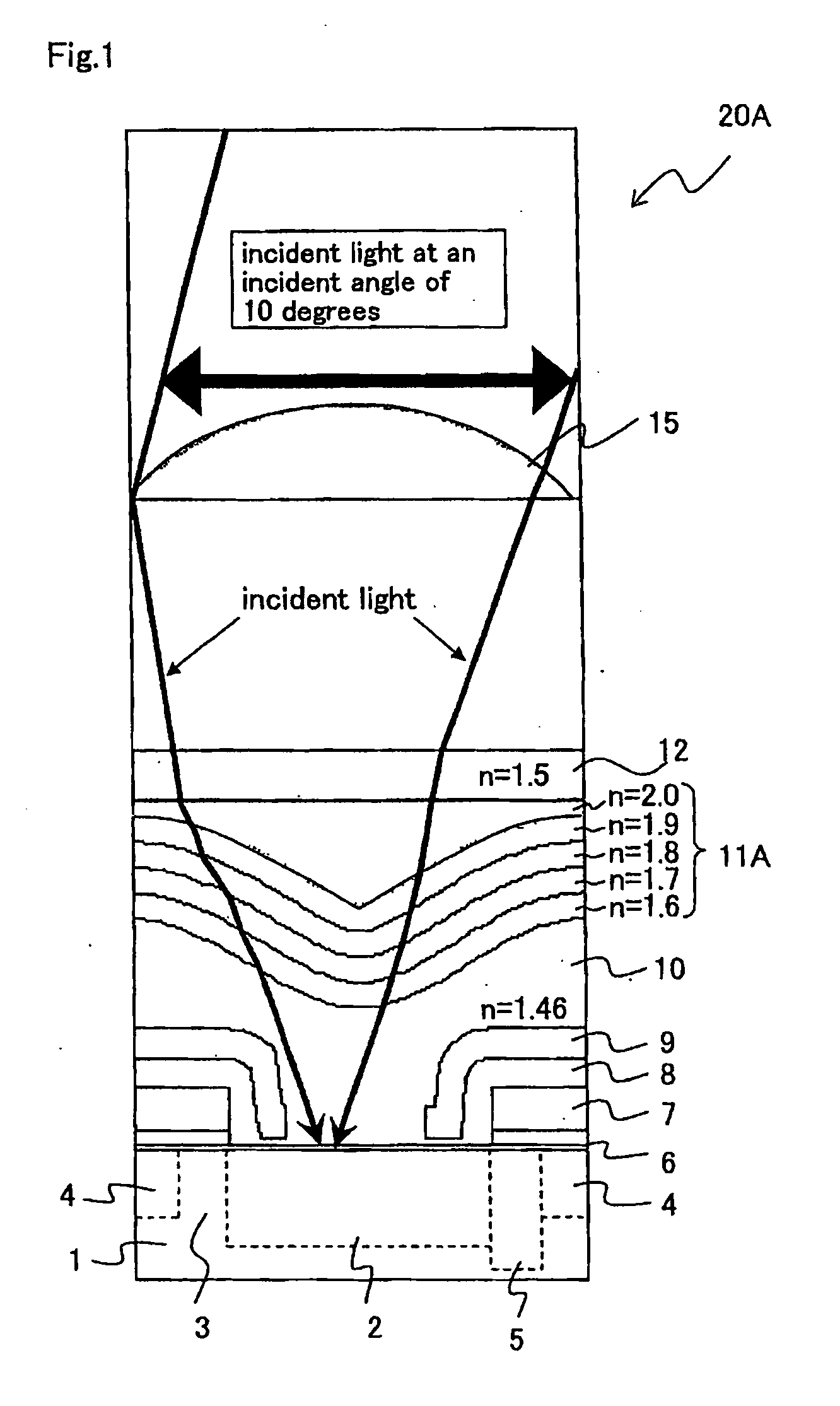
[0094]FIG. 1 is an essential part longitudinal cross sectional view of one pixel schematically illustrating a light focusing simulation result of a solid-state image capturing device according to Embodiment 1 of the present invention.

[0095]In FIG. 1, a solid-state image capturing device 20A according to Embodiment 1 is provided with impurity diffusion layers, such as a photoelectric conversion section 2, a readout gate section 3 next to it, a CCD transfer channel 4 next to it, and a channel stopper 5 next to it, for each unit pixel on a surface side of a semiconductor substrate 1. A transfer electrode 7 is formed above the readout gate section 3 and the CCD transfer channel 4 with an insulation film 6 interposed therebetween. For example, in a case of a CCD, the transfer electrode 7 is formed above the semiconductor substrate 1 between the adjacent photoelectric conversion sections 2 with the insulation film 6 interposed therebetween. The transfer electrode 7 has a function to read ...

embodiment 2

[0124]While the case where the downward convex inner-layer lens 11A is formed using a concave shaped well (difference in level) between the photoelectric conversion section 2, and the transfer electrode 7 and light shielding film 9 has been described in Embodiment 1, a case where an upwards convex inner-layer lens is formed by transfer printing will be described in Embodiment 2.

[0125]FIG. 3 is a longitudinal cross sectional view schematically illustrating an exemplary essential structure of one pixel of a CCD type solid-state image capturing device according to Embodiment 2 of the present invention. In FIG. 3, the same reference numbers are used, for the description of the constituent members, as those of FIG. 1, since they have the same function and effect.

[0126]As illustrated in FIG. 3, a CCD type solid-state image capturing device 20B according to Embodiment 2 is provided with impurity diffusion layers, such as a photoelectric conversion section 2, a readout gate section 3 next t...

embodiment 3

[0153]FIG. 7 is a block diagram illustrating an exemplary diagrammatic structure of an electronic information device as Embodiment 3 of the present invention, including the solid-state image capturing device according to Embodiment 1 or 2 of the present invention used in an image capturing section.

[0154]In FIG. 7, the electronic information device 90 according to Embodiment 3 of the present invention includes: a solid-state image capturing apparatus 91 for performing various signal processing on an image capturing signal from the solid-state image capturing devices 20A, 20B, 20C or 20D according to Embodiments 1 and 2 described above so as to obtain a color image signal; a memory section 92 (e.g., recording media) for data-recording a color image signal from the solid-state image capturing apparatus 91 after a predetermined signal process is performed on the color image signal for recording; a display section 93 (e.g., a color liquid crystal display apparatus) for displaying the col...


PUM


Abstract

A solid-state image capturing device according to the present invention includes: a photoelectrical conversion section formed in a semiconductor substrate or in a substrate area provided on a substrate; a first transparent film provided on the photoelectrical conversion section; and a lens provided at a position above the first transparent film corresponding to the photoelectrical conversion section, where the lens is formed by using a second transparent film layered by changing a refractive index successively or incrementally, and at least one of top and bottom surfaces of the second transparent film is formed in a convex shape.

Description

[0001]This nonprovisional application claims priority under 35 U.S.C. §119(a) to Patent Application No. 2008-104138 filed in Japan on Apr. 11, 2008, the entire contents of which are hereby incorporated by reference.BACKGROUND OF THE INVENTION[0002]1. Field of the Invention[0003]The present invention relates to a solid-state image capturing device comprising semiconductor elements for performing a photoelectric conversion on and capturing an image light from an object, a method for manufacturing the solid-state image capturing element, and an electronic information device, such as a digital camera (e.g., digital video camera and digital still camera), an image input camera, a scanner device, a digital copying machine, a facsimile machine and a camera-equipped cell phone device, having the solid-state image capturing device as an image input device used in an image capturing section of the electronic information device.[0004]2. Description of the Related Art[0005]The conventional soli...

Claims


Application Information

Patent Timeline
IPC IPC(8): H01L31/0232H01L21/00H01L27/14H04N5/335H04N5/369H04N5/372H04N101/00
CPCH01L27/14623H01L27/14685H01L27/14632H01L27/14627
Inventor NAKAI, JUNICHIKONISHI, TOMOHIRO
Owner SMARTSENS TECH (SHANGHAI) CO LTD
Learn More