
System and method for growing nanotubes with a specified isotope composition via ion implantation using a catalytic transmembrane

a technology of ion implantation and nanotubes, which is applied in the field of nanotubes, can solve the problems of not being able to propose a good solution for growing cnts, unable to manufacture a high-purity single pure isotope of carbon e.g. 1, and achieve the effect of avoiding erosion or contamination

Active Publication Date: 2009-10-08
THE ARIZONA BOARD OF REGENTS ON BEHALF OF THE UNIV OF ARIZONA +1
View PDF18 Cites 35 Cited by
  • Summary
  • Abstract
  • Description
  • Claims
  • Application Information

AI Technical Summary

Benefits of technology

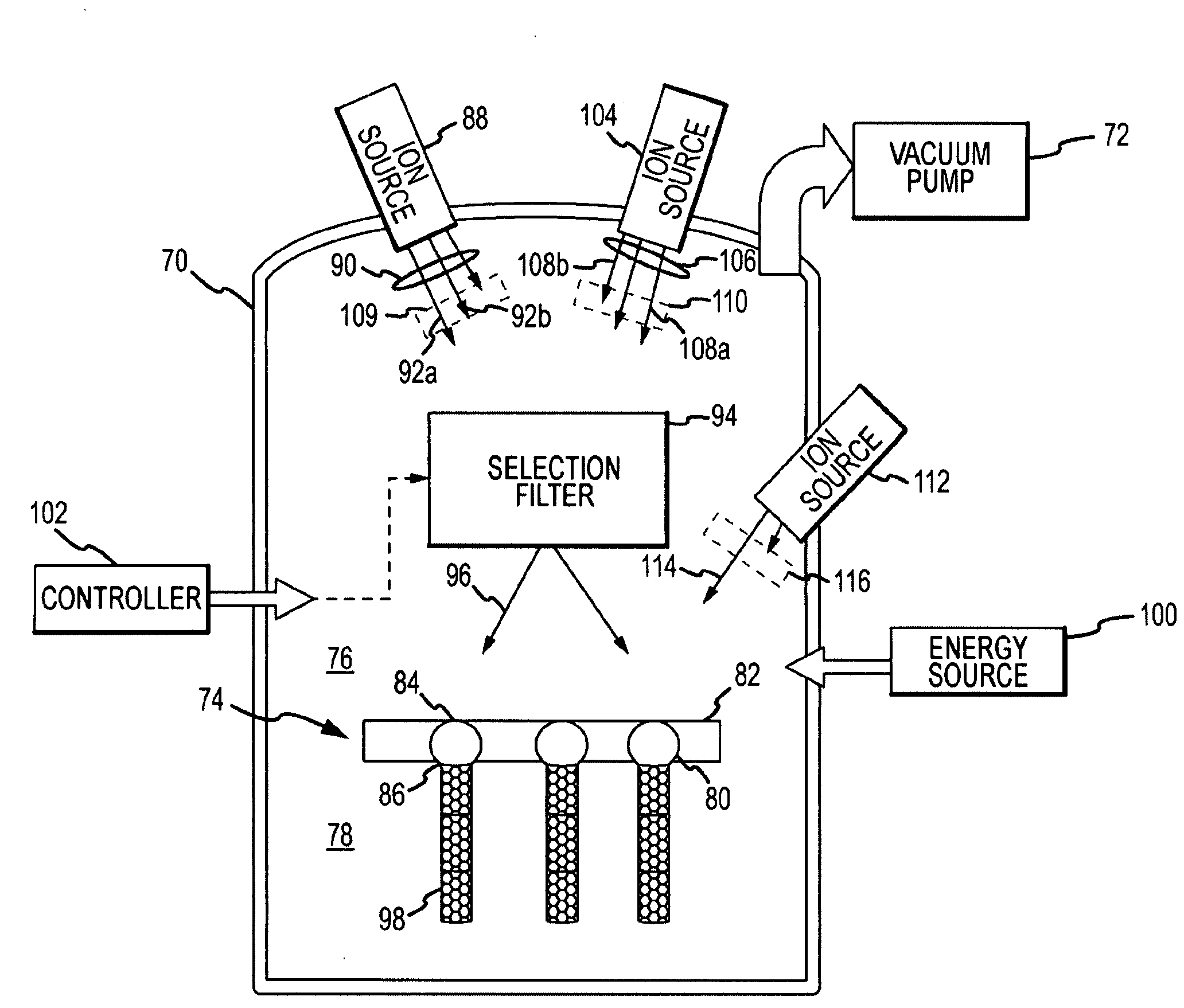
[0013]The filter may be configured to pass ions of a single isotope such as 12C atoms or a unique molecular combination of different isotopes such as 26Al14N to grow a pure nanotube from that atom or molecule. The filter could be reconfigured to pass a different single isotope or molecule such as 13C or 26Al15N to form isotope-junctions 12C-13C and molecular-junctions 26Al14N-26Al15N, respectively. The source(s) and filter could be configured to switch between specific isotopes of different elements. e.g. 12C-10B10B14N to form element-junctions. These structures can be doped with dopant atoms using different means. The source may include a small amount of dopant material that looks like the desired isotope to the filter and thus is included as part of the subset directed towards the catalysts. For example, a small amount of 11B1H could be included with a carbon source. If the filter is configured to pass ions having a mass number of twelve, 12C and 11B1H will be directed towards the substrate. Upon implantation in the catalyst, the H atom will break away leaving 11B dopant atoms in the 12C lattice. This is an effective approach for achieving uniform doping. Alternately, a separate source of dopant ions may be provided and directed through the same filter. By controlling the source, the dopant concentration can be varied or turned on and off entirely to selectively dope the nanotube. A separate source of dopant ions and separate selection filter can be used to dope the nanotube lattice with dopant atoms that do not look like the selected isotopes. If isotope selection of the dopant ions is not required, the dopant source can be directed at the substrate without filtering.
[0015]The catalytic membrane supports the catalysts so that ions are implanted on one side and nanotubes grown on the other to avoid erosion or contamination of the grooving nanotube caused by direct exposure to the ion beam. In one configuration, the catalysts are attached to the underside of a membrane formed of a non-porous material. The ions must penetrate through the membrane and be implanted into the catalysts. Wells may be formed in the membrane and the catalysts placed therein to reduce the amount of material the ion beam must penetrate and to provide a defined region for growing each nanotube. Cavities may be formed in the membrane and catalysts attached to an inner wall facing the implantation region. The ions are implanted through the membrane into the catalysts to grow nanotubes within the cavities. In another configuration, the membrane is formed of a porous material. The catalysts may fill the pores so that the ion beam implants ions into the catalysts on the top side of the membrane to grow nanotubes on the underside of the membrane away from the ion beam. A layer of catalyst material may be formed over the membrane facing the ion source. Ions are implanted into the catalyst layer causing nanotubes to grow through the pores in the membrane and away from the ion beam. If catalysts are attached to the underside of the membrane, the ions will pass through the pores into the catalysts to grow nanotubes away from the ion beam. Use of the catalytic transmembrane to separate ion implantation from nanotube growth prevents the ion beam from damaging the nanotubes. There are many different ways to configure the catalytic transmembrane.

Problems solved by technology

CVD generally produces MWNTs or SWNTs of relatively poor quality due mostly to the poorly controlled diameters of the nanotubes.
However, current technologies cannot manufacture a high-purity single pure isotope of carbon e.g. ˜100% C12.
Investigations such as Shiomi's “assume” the existence of a CNT having the desired isotope junctions and purity but have not proposed a good solution for growing CNTs of a pure isotope much less CNTs having isotope junctions.

Method used


Image

  • System and method for growing nanotubes with a specified isotope composition via ion implantation using a catalytic transmembrane
  • System and method for growing nanotubes with a specified isotope composition via ion implantation using a catalytic transmembrane
  • System and method for growing nanotubes with a specified isotope composition via ion implantation using a catalytic transmembrane

Examples


case 1

-Isotope or Unique Molecular Combination

[0039]A simple yet very important nanotube structure 120 is that of a pure single-isotope or unique molecular combination of two or more different isotopes as shown in FIG. 6a. These types of nanotube structures may be useful in a wide range of devices including semiconductor, spin transport, or optical pumping devices.

[0040]In an exemplary embodiment, a source 50 emits a primary beam 54 including 12C, 13C and perhaps 14C isotopes of carbon ions. The filter 68 is configured to pass only the desired single isotope, e.g. 12C. In other words, the subset includes only the single 12C isotope. The resulting nanotubes can be grown with a purity of at least 99.9% 12C. A small amount of unintentional contaminants (the blocked isotopes) may pass through or around the filter but the amount is very small.

[0041]Carbon nanotubes are of particular commercial interest. Naturally occurring carbon includes approximately 98.9% 12C, 1% 13C and 10−10% or less 14C....

case 2

m Doping of Single-Isotope or Unique Molecular Combination

[0043]Another important nanotube structure 122 is that of a single isotope or single unique molecular combination of two or more different isotopes uniformly doped with a dopant atom as shown in FIG. 6b. The dopant atoms 124 take the place of element atoms in the lattice. These types of nanotube structures may be useful in semiconductor devices such as diode or transistor designs, or optical pumping devices, such as quantum cascade lasers.

[0044]To provide a continuous uniform doping of, for example, a 12C nanotube, the carbon source 50 might include a dopant molecule having the same weight as the desired element isotope, in which case the dopant molecule will pass through the isotope selection filter. For example, if the selection filter is tuned to pass ions with atomic weight of 12, both 12C ions and 11B1H dopant molecule ions will pass. The 11B1H molecule will break apart when it collides with the catalysts 72 with the B11...

case 3

ive Doping of Single-Isotope or Unique Molecular Combination

[0045]Another important nanotube structure 126 is that of a single-isotope or single unique molecular combination of two or more different isotopes selectively doped with a dopant atom as shown in FIG. 6c. The dopant atoms 128 take the place of element atoms in the lattice in desired zones. These types of nanotube structures may be useful in nanoelectronic and spintronic devices.

[0046]To provide selective doping of, for example, a 12C nanotube, the source 50 emits a primary beam including multiple isotopes 12C, 13C and 14C. The filter directs only the 12C isotope to the membrane. In one embodiment, the secondary ion source 104 emits a primary ion beam including multiple dopant isotopes, e.g. 11B1H and 12B1H directed to the same filter. The 11B1H ions look like 12C ions and are directed towards the substrate where the 11B ions are implanted into the catalyst and form dopant sites in the 12C lattice. The primary beam of dopan...


PUM

PropertyMeasurementUnit
Fractionaaaaaaaaaa
Digital informationaaaaaaaaaa
Lengthaaaaaaaaaa

Abstract

An ion source(s) is configured to generate ions from one or more elements including a plurality of different isotopes or unique molecular combinations of two or more different isotopes from at least one of the selected elements. A selection filter(s) directs a subset of the ions onto a catalytic transmembrane to grow nanotubes of a specific isotope composition on the opposite side of the transmembrane. The nanotubes may be uniformly or selectively doped with dopant atoms. A controller can configure the selection filter(s) to sequentially pass different subsets of ions to form isotope, molecular or element junctions in the growing nanotubes.

Description

CROSS-REFERENCE TO RELATED APPLICATIONS[0001]This application claims benefit of priority under 35 U.S.C. 120 as a continuation-in-part of co-pending U.S. application Ser. No. 12 / 061,317 entitled “System and Method for Nanotube Growth via Ion Implantation using a Catalytic Transmembrane” filed on Apr. 2, 2008, the entire contents of which are incorporated by reference.BACKGROUND OF THE INVENTION[0002]1. Field of the Invention[0003]This invention relates to nanotube (NT) growth of carbon and other materials using an ion implantation process, and more particular to the growth of nanotubes with a specified isotope composition using a selection filter and catalytic transmembrane.[0004]2. Description of the Related Art[0005]Carbon nanotubes (CNTs) have stimulated a great deal of interest in the microelectronic and other industries because of their unique properties including tensile strengths above 35 GPa, elastic modulus reaching 1 TPa, higher thermal conductivity than diamond, ability t...

Claims


Application Information

Patent Timeline
IPC IPC(8): C23C14/48
CPCB82Y30/00B82Y40/00C01B21/064C01B2202/30C01B31/36C01B33/02C01B35/02C01B31/0233C01B32/162
Inventor BARKER, DELMAR L.BECK, JOHN WARREN
Owner THE ARIZONA BOARD OF REGENTS ON BEHALF OF THE UNIV OF ARIZONA
Learn More