Positioning control unit and optical disk drive
a technology of positioning control unit and optical disk drive, which is applied in the direction of digital signal error detection/correction, instruments, recording signal processing, etc., can solve the problems of limited characteristic of the drive machinery system that drives the moving member, inability to achieve sufficient accuracy or performance in many cases, and difficulty in improving the tracking performance of the moving member. achieve the effect of increasing the fluctuation of the target position and high accuracy
- Summary
- Abstract
- Description
- Claims
- Application Information
AI Technical Summary
Benefits of technology
Problems solved by technology
Method used
Image

Examples
first embodiment
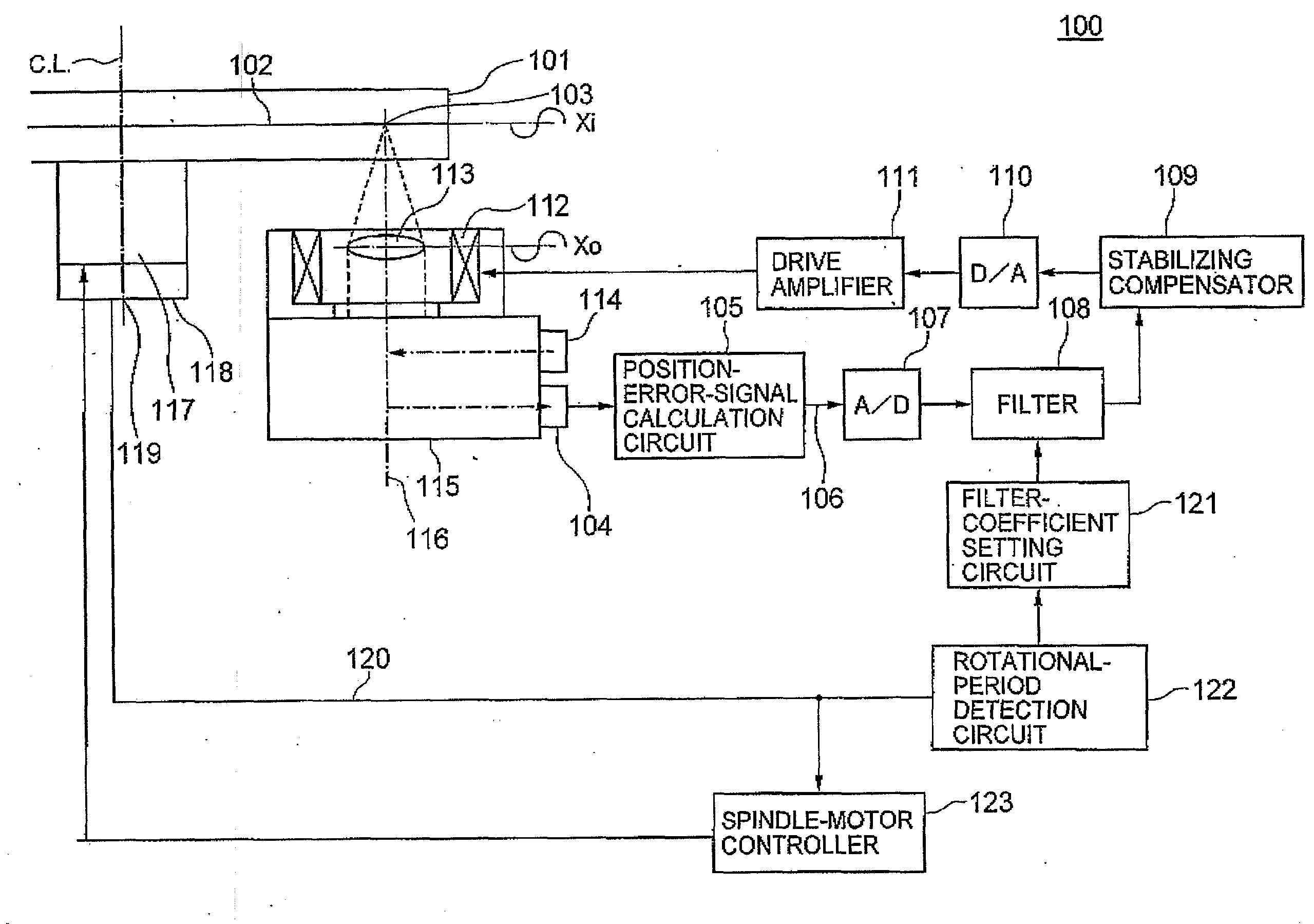
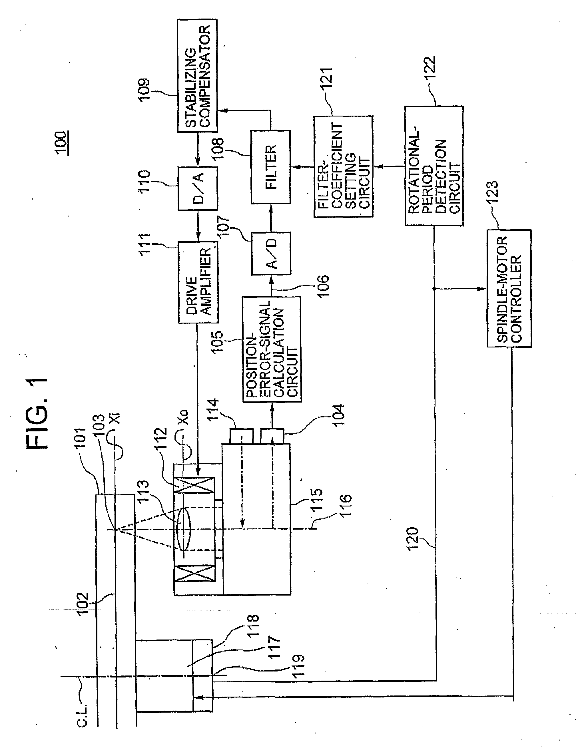
[0030]Exemplary embodiments of the present invention will be described in detail hereinafter with reference to the drawings. FIG. 1 shows part of the configuration of an optical disc drive including a positioning control unit according to the present invention. In the same drawing, the basic configuration of the axial-tracking control unit portion of the optical disc drive is extracted for illustration. The optical disc drive 100 includes a position-error-signal calculation circuit 105, an A / D converter 107, a filter 108, a stabilizing compensator 109, a D / A converter 110, a drive amplifier 111, an optical head 115, a spindle motor 117, a filter-coefficient setting circuit 121, a rotational-period detection circuit 122, and a spindle-motor controller 123. The optical head 115 includes a photodetector 104, a focus actuator 112, an objective lens 113, and a laser light source 114.
[0031]The photodetector 104, position-error-signal calculation circuit 105 and A / D converter 107 configure...
second embodiment
[0080]Although the laser-focused-beam spot 103 is moved from the first surface 196 to the second surface 197 of the optical disc medium 101 to measure the thickness of the optical disc medium 101 based on the time difference of passing through both the surfaces in the second embodiment the configuration is not limited thereto. Since the optical disc medium compliant with the physical standard of HD DVD and DVD, for example, has the structure obtained by bonding together two substrates having a thickness of 0.6 mm, the optical disc medium has a practical thickness double the thickness of a single substrate. Since the time t2−t1 corresponds to the thickness from the first surface 196 of the optical disc medium 101 to the information recording layer 102, i.e., the substrate thickness in FIG. 14, a configuration may be employed wherein the thickness detection circuit 191 outputs, after observing the focus S-character signal 1003 corresponding to the information recording layer 102 at ti...
PUM
| Property | Measurement | Unit |
|---|---|---|
| thickness | aaaaa | aaaaa |
| diameter | aaaaa | aaaaa |
| wavelength | aaaaa | aaaaa |
Abstract
Description
Claims
Application Information
 - R&D
- Intellectual Property
- Life Sciences
- Materials
- Tech Scout
- Unparalleled Data Quality
- Higher Quality Content
- 60% Fewer Hallucinations
Browse by: Latest US Patents, China's latest patents, Technical Efficacy Thesaurus, Application Domain, Technology Topic, Popular Technical Reports.
© 2025 PatSnap. All rights reserved.Legal|Privacy policy|Modern Slavery Act Transparency Statement|Sitemap|About US| Contact US: help@patsnap.com