
Sensor-equipped axle unit having a built-in motor of in-wheel type

Active Publication Date: 2009-09-24
NTN CORP
View PDF26 Cites 64 Cited by
  • Summary
  • Abstract
  • Description
  • Claims
  • Application Information

AI Technical Summary

Benefits of technology

[0011]An object of the present invention is to provide a sensor equipped axle unit having an in-wheel type motor built therein, in which forces acting in three axis directions perpendicular to each other at a point of contact of the vehicle drive wheel with the road surface are measured, with high sensitivity, from the status of a component part, associated with the drive abort of the automotive vehicle, so that the vehicle body attitude stability control of the electromotor driven automotive vehicle can be accomplished with high accuracy. It is to be noted that in the case of the electromotor driven automotive vehicle, the component part associated with the drive abort of the automotive vehicle includes a tire, a wheel, a hub assembly, a drive source and a brake assembly.

Problems solved by technology

In addition, it may be available in the form of an air drag dependent on the travelling velocity and an aerodynamic force brought about by a wind blowing in nature, but those are low in steady state.
However, measurement of the forces acting in the automotive vehicle with sensors fitted to the vehicle body structure such as hitherto practiced is nothing other than measurement of vibrations transmitted to the vehicle body structure through the suspension system and the chassis and, therefore, a time lag tends to occur in the resultant measurement.
Because of this, a problem has been encountered with in that the response to control tends to be delayed if the resultant measurement involving the time lag is utilized in the stability control.

Method used


Image

  • Sensor-equipped axle unit having a built-in motor of in-wheel type
  • Sensor-equipped axle unit having a built-in motor of in-wheel type
  • Sensor-equipped axle unit having a built-in motor of in-wheel type

Examples


Embodiment Construction

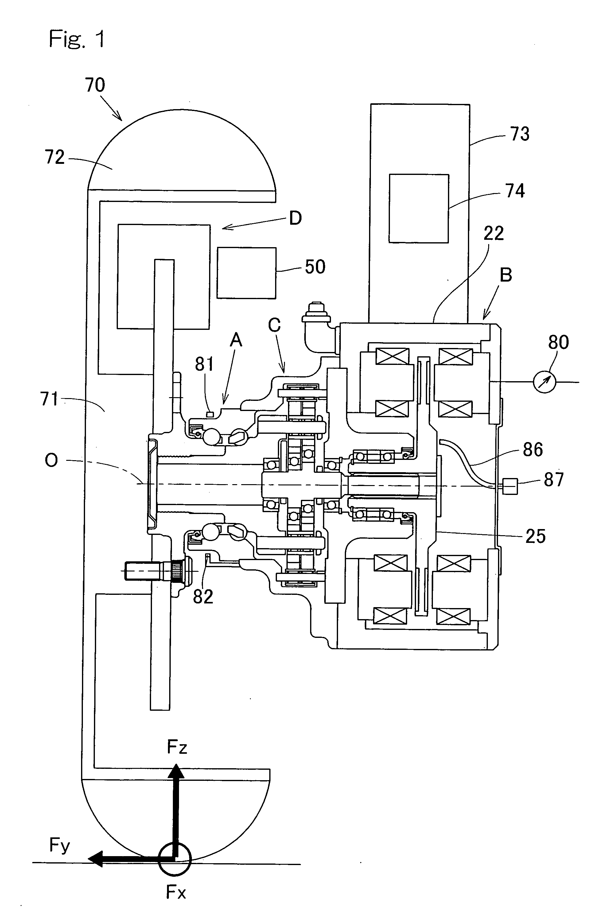
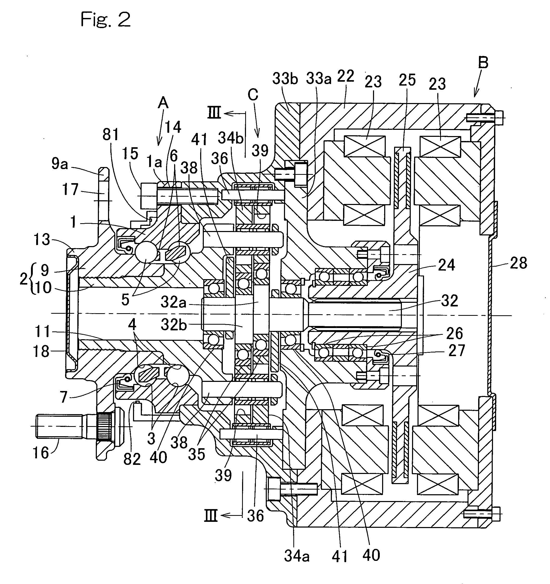
[0042]A preferred embodiment of the present invention will now be described in detail with particular reference to FIGS. 1 to 9. At the outset, a summary of this preferred embodiment will first be described with particular reference to FIG. 1. The illustrated sensor equipped axle unit having an in-wheel type motor built therein includes a hub bearing assembly A for rotatably supporting a hub of a vehicle drive wheel 70, an electric motor B as a source of rotatory drive, a reduction gear unit C for reducing the rotation of the electric motor B and then transmitting it to the hub and a brake assembly D for applying a braking force to the hub, all being arranged in alignment with a center axis O of the vehicle drive wheel 70. What has just been stated here does not necessarily means that all of the component elements are positioned on the center axis O, but means that those component parts functionally cooperate with each other relative to the center axis O. It is to be noted that in t...


PUM


Abstract

A sensor equipped axle unit having an in-wheel type motor built therein, in which a hub bearing assembly (A), an electric motor (B), a reduction gear unit (C) and a brake assembly (D) are arranged coaxially on a center axis of a vehicle drive wheel. Sensors (80, 81 and 82) are provided for measuring forces Fx, Fy and Fz acting at a point of contact of the vehicle drive wheel (70) and a road surface in three axis directions perpendicular to each other, respectively, from the status of at least one of the hub bearing assembly (A), the electric motor (B), the reduction gear unit (C) and the brake assembly (D). Results of such measurement are utilized for a suspension control, an ABS control and any other control.

Description

BACKGROUND OF THE INVENTION[0001]The present invention relates to a sensor equipped axle unit having a built-in motor of in-wheel type including a hub bearing assembly, a reduction gear unit and an electric motor combined together in a unitary structure and, more particularly, to the control technology in controlling the traveling stability of an electrically driven automotive vehicle.[0002]As means to reduce the environmental loading, the automotive vehicle is expected to transform from a power type utilizing a combustion engine to a different power type utilizing an electric motor in the future. Under these circumstances, the axle unit having an in-wheel type motor built therein has been suggested as a wheel support bearing assembly for the support of a vehicle drive wheel of an electrically powered automotive vehicle. (See, for example, the Patent Documents 1 and 2 quoted below.) When this suggested axle unit having the in-wheel type motor built therein is employed in the vehicle...

Claims


Application Information

Patent Timeline
IPC IPC(8): B60K7/00
CPCB60G2204/30B60G2300/50B60K7/0007B60K17/043B60K17/046B60K2007/0038Y02T10/7258B60T8/329B60T13/741F16D65/18F16D2121/24F16D2125/40B60K2007/0092B60L3/0061B60L3/0076B60L7/26B60L15/2009B60L2220/44B60L2220/50B60L2240/421B60L2240/429B60L2240/461B60L2270/145Y02T10/64Y02T10/72
Inventor AKAMATSU, YOSHINOBU
Owner NTN CORP
Learn More