Eureka AIR delivers breakthrough ideas for toughest innovation challenges, trusted by R&D personnel around the world.

System, method and apparatus for lean combustion with plasma from an electrical arc

a technology of electrical arc and plasma combustion, which is applied in the direction of marine propulsion, vessel parts, vessel construction, etc., can solve the problems of ramjets and scramjets, current combustors cannot hold flames during lean combustion conditions, and one successful scramjet has flown since the beginning

Active Publication Date: 2009-09-24
FORET PLASMA LABS
View PDF1 Cites 118 Cited by
  • Summary
  • Abstract
  • Description
  • Claims
  • Application Information

AI Technical Summary

Problems solved by technology

There are many problems associated with lean fuel combustion or low BTU gas combustion in gas turbine engines.
However, only one successful Scramjet has been flown since the beginning of aviation.
The major problem with ramjets and scramjets can be traced back to the early problem of flame holding or preventing engine flame out.
In addition, no matter which configuration is chosen for Hypersonic Flight a problem remains—transition from subsonic to supersonic and finally hypersonic flight will require several different engines.
However, current combustors cannot hold a flame during lean combustion conditions.
Likewise, low BTU fuel such as syngas is difficult to combust in current gas turbine engines.
The problem with syngas is that it is not widely available.
Typical gasifiers are very large and extremely expensive.
However, this would create a detrimental effect on the compressor turbine if operated at supersonic combustion utilizing an intense igniter such as a plasma torch.
However, attempting to achieve lean combustion within current internal combustion (“IC”) engine designs may lead to low reaction rates, flame extinction (“Flame Out”), instabilities, and mild heat release.

Method used


Image

  • System, method and apparatus for lean combustion with plasma from an electrical arc
  • System, method and apparatus for lean combustion with plasma from an electrical arc
  • System, method and apparatus for lean combustion with plasma from an electrical arc

Examples


Embodiment Construction

[0033]While the making and using of various embodiments of the present invention are discussed in detail below, it should be appreciated that the present invention provides many applicable inventive concepts that can be embodied in a wide variety of specific contexts. The specific embodiments discussed herein are merely illustrative of specific ways to make and use the invention and do not delimit the scope of the invention.

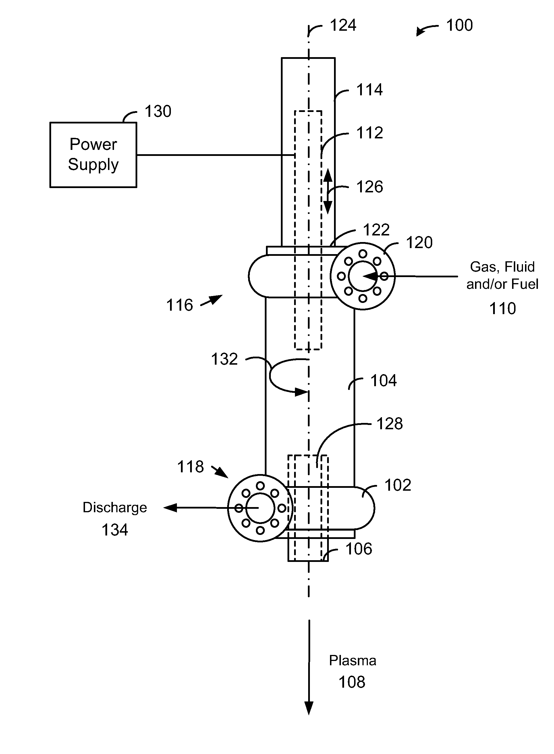
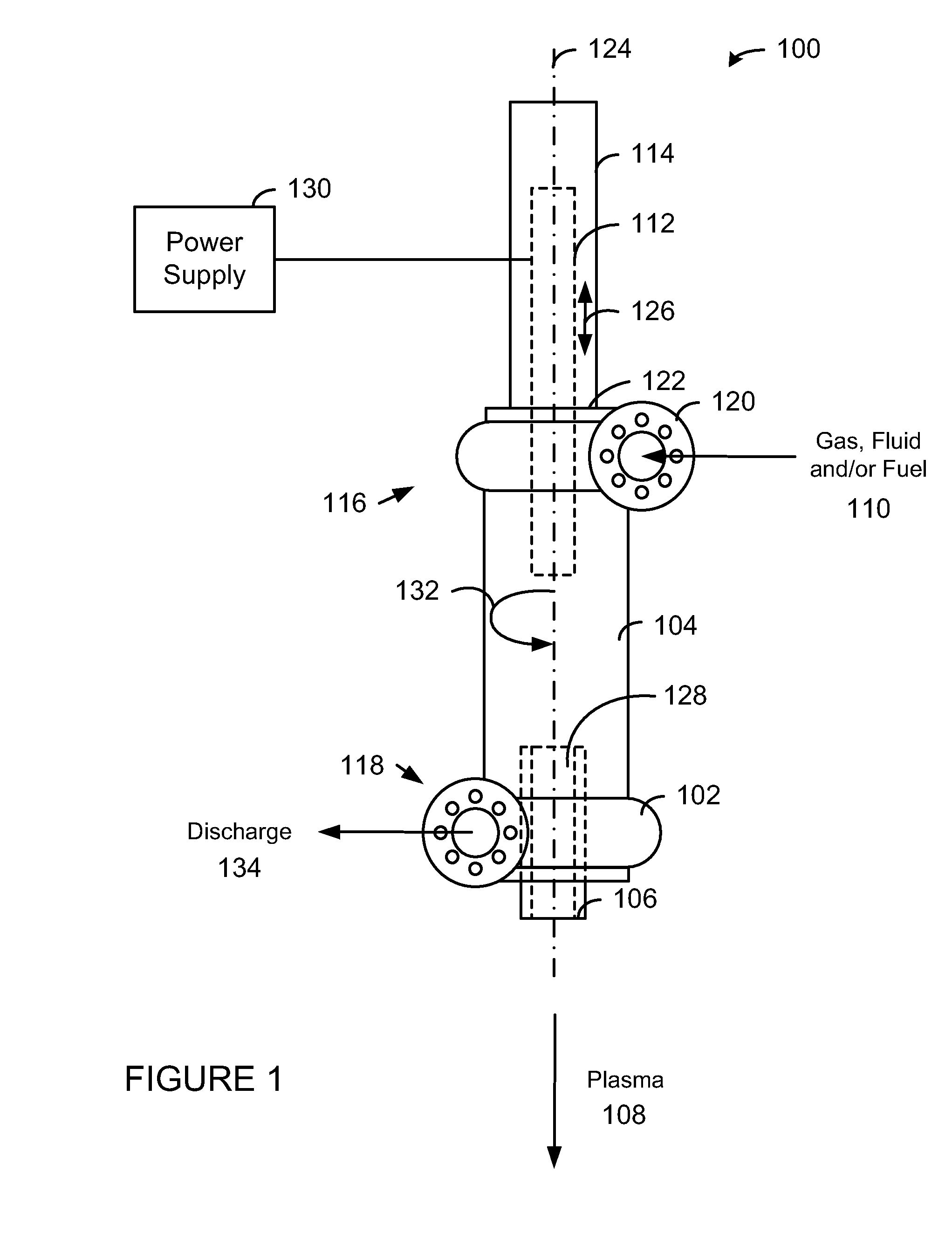
[0034]Now referring to FIG. 1, a plasma arc torch 100 in accordance with one embodiment of the present invention is shown. The plasma arc torch 100 is a modified version of the ARCWHIRL® device disclosed in U.S. Pat. No. 7,422,695 (which is hereby incorporated by reference in its entirety) that produces unexpected results. More specifically, by attaching a discharge volute 102 to the bottom of the vessel 104, closing off the vortex finder, replacing the bottom electrode with a hollow electrode nozzle 106, an electrical arc can be maintained while discharging plas...


PUM


Abstract

The present invention provides a plasma arc torch that can be used for lean combustion. The plasma arc torch includes a cylindrical vessel, an electrode housing connected to the first end of the cylindrical vessel such that a first electrode is (a) aligned with a longitudinal axis of the cylindrical vessel, (b) extends into the cylindrical vessel, and (c) can be moved along the longitudinal axis, a linear actuator connected to the first electrode to adjust a position of the first electrode, a hollow electrode nozzle connected to the second end of the cylindrical vessel such that the center line of the hollow electrode nozzle is aligned with the longitudinal axis of the cylindrical vessel, and wherein the tangential inlet and the tangential outlet create a vortex within the cylindrical vessel, and the first electrode and the hollow electrode nozzle crate a plasma the discharges through the hollow electrode nozzle.

Description

FIELD OF THE INVENTION[0001]The present invention relates generally to gas turbine engines. More specifically, the present invention relates to a supersonic lean combustion plasma steam reforming turbine engine that will combust low BTU gas such as landfill gas, biogas, blast furnace gas, coke oven gas and syngas.PRIORITY CLAIM[0002]This patent application is non-provisional patent application of U.S. provisional patent application Ser. No. 61 / 027,879 filed on Feb. 12, 2008 and entitled, “System, Method and Apparatus for Lean Combustion with Plasma from an Electrical Arc.”BACKGROUND OF THE INVENTION[0003]There are many problems associated with lean fuel combustion or low BTU gas combustion in gas turbine engines. With the successful flight of the X-43A, hypersonic flight has achieved several technological goals and entered a new era. With further developments, it will reach Technology Readiness Level. However, FAA and EPA emission regulations in addition to the cost of fossil-based ...

Claims


Application Information

Patent Timeline
Patent Type & Authority Applications(United States)
IPC IPC(8): B64G1/40F02C7/264
CPCY02T50/678F23R2900/00009F23R3/58H05H1/24F23R2900/00002F02C7/266F02K9/425H05H1/32F23R3/007Y02E50/12F01D13/00F02C3/14F02K3/12Y02E50/10B64G1/413B64G1/405G21D5/02H05H1/34B64G1/415
Inventor FORET, TODD
Owner FORET PLASMA LABS
Why Eureka
Eureka Blog
Learn More