Eureka AIR delivers breakthrough ideas for toughest innovation challenges, trusted by R&D personnel around the world.

Hardware Monitoring and Decision Making for Transitioning In and Out of Low-Power State

a technology of low-power state and monitoring protocol, applied in the field of computer design, can solve the problems of invalidation, c1-c5 state power saving efficiency becoming more limited, and reducing power consumption by sizing down, so as to achieve optimal balance between power saving and performance. , the effect of more efficiency

Active Publication Date: 2009-09-17
MEDIATEK INC
View PDF11 Cites 258 Cited by
  • Summary
  • Abstract
  • Description
  • Claims
  • Application Information

AI Technical Summary

Benefits of technology

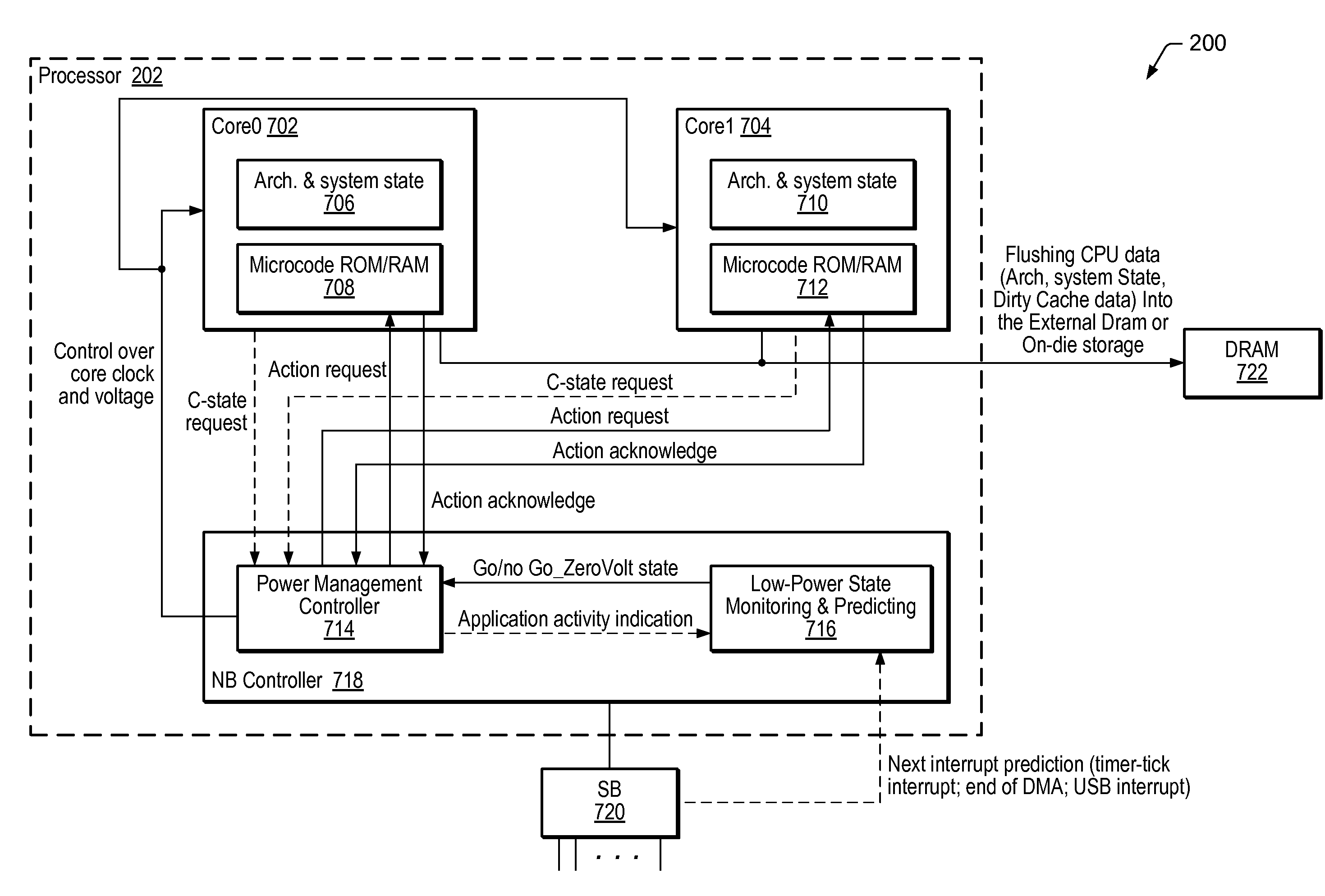
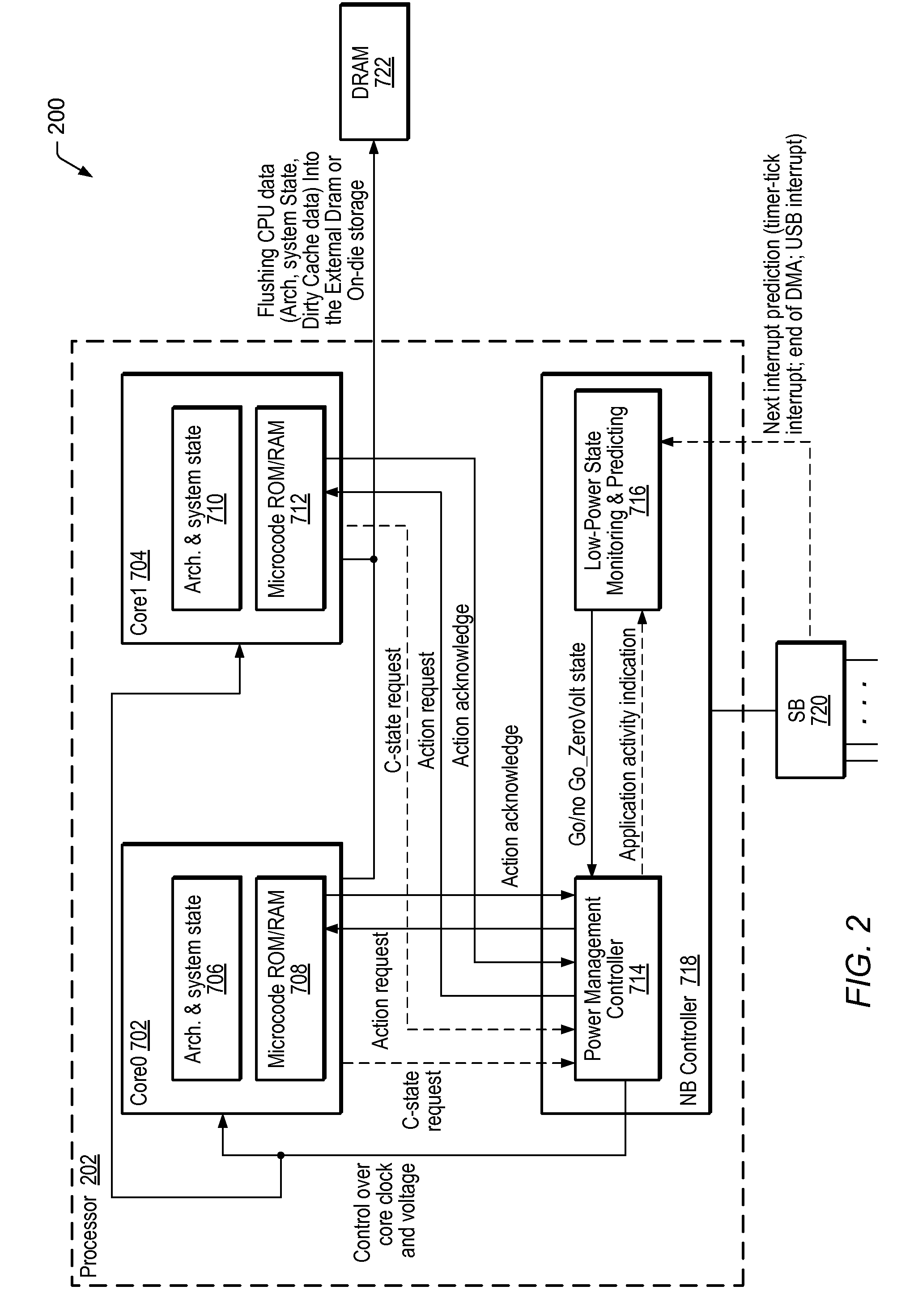
[0022]Thus, by monitoring state residency and predicting various types of interrupts (e.g. TT interrupts, end-of-DMA interrupts, and / or I / O based interrupts), processing units, processors, and / or processor cores may be transitioned into various target power-states with more efficiency, achieving a more optimal balance between power savings and performance.

Problems solved by technology

However, none of these states completely eliminates the static power component consumed by the processor.
Therefore the efficiency of C1-C5 states for power saving is becoming more limited for advanced CPU manufacturing process technologies and smaller transistor geometries.
For example, power consumption may be lowered by sizing-down, invalidating, and eventually turning-off the L2 cache by lowering the retention voltage to a level lower than is needed to retain L2 contents.
While this offers one possible solution in eliminating the massive L2 component from the static power consumption budget, it does not eliminate the power consumption contribution of smaller arrays (e.g. L1 cache) or regular logic, thus maintaining static power at fairly high level for advanced (45 nm and lower) processes.

Method used


Image

  • Hardware Monitoring and Decision Making for Transitioning In and Out of Low-Power State
  • Hardware Monitoring and Decision Making for Transitioning In and Out of Low-Power State
  • Hardware Monitoring and Decision Making for Transitioning In and Out of Low-Power State

Examples


Embodiment Construction

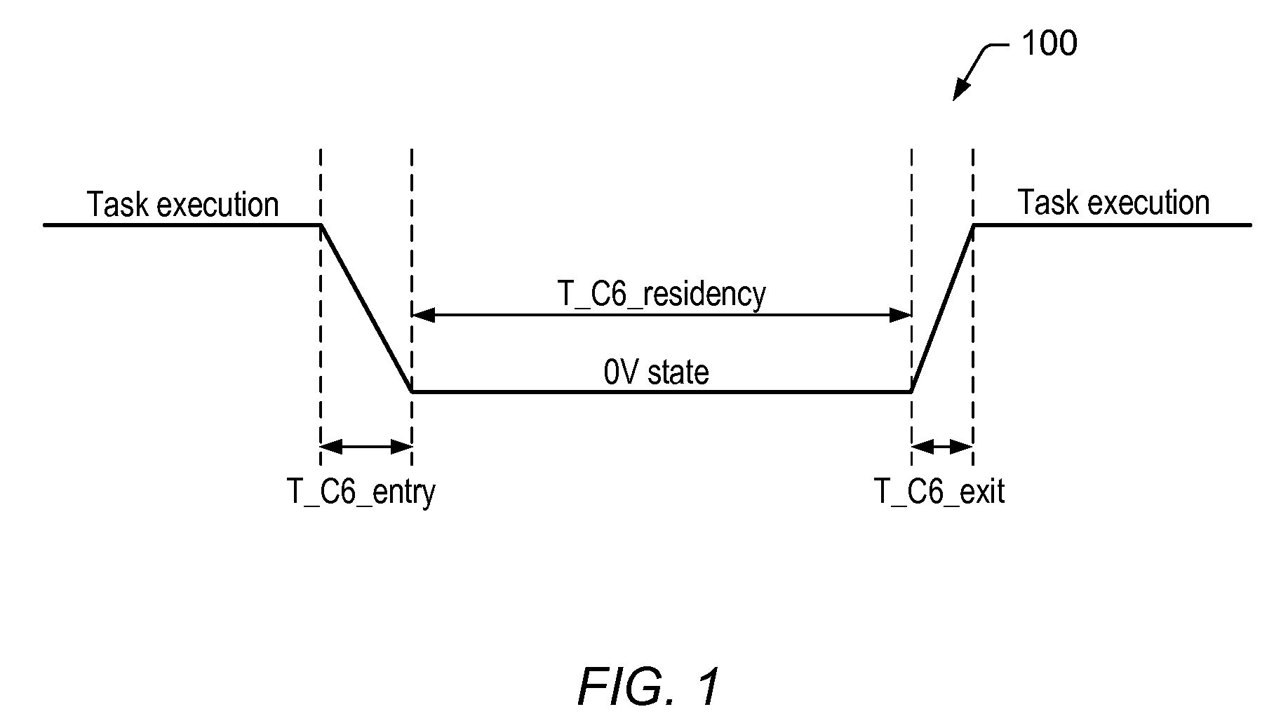
[0033]A zero-power or zero-volt (0V) state, otherwise referred to as C6-state may allow for complete elimination of both dynamic and static components of power consumption, by transitioning a processor core (or multiple processor cores) to a state in which the respective supply voltage of the processor core may be reduced to 0V, and the operating clock used by the processor core may be uncoupled from the processor core, or gated off from the processor core, meaning simply that the clock signal may be prevented from reaching the processor core. Alternately, the operating clock used by the processor may be completely turned off, e.g. when no other system components depend on the same clock. C6-state is not equivalent to system sleep, e.g. state S3 where most of the system is powered down, and restoration to the operating state (C0-state) may require an extended period of time, oftentimes many seconds. C6-state may be applied to a single-core processor or to any core or group of cores ...


PUM


Abstract

A power management controller (PMC) that interfaces with a processor comprising one or more cores. The PMC may be configured to communicate with each respective core, such that microcode executed by the respective processor core may recognize when a request is made to transition the respective core to a target power-state. For each respective core, the state monitor may monitor active-state residency, non-active-state residency, Direct Memory Access (DMA) transfer activity associated with the respective core, Input / Output (I / O) processes associated with the respective core, and the value of a timer-tick (TT) interval associated with the respective core. The status monitor may derive respective status information for the respective core based on the monitoring and indicate whether the respective core should be allowed to transition to the corresponding target power-state. The PMC may transition the respective processor core to the corresponding target power-state accordingly.

Description

PRIORITY CLAIM[0001]This application is a continuation-in-part of U.S. utility application Ser. No. 12 / 045,764 titled “A Protocol for Transitioning In and Out of Zero-Power State” filed Mar. 11, 2008, whose inventors were Alexander Branover, and Rajen S. Ramchandani, and which is hereby incorporated by reference in its entirety as though fully and completely set forth herein.BACKGROUND OF THE INVENTION[0002]1. Field of the Invention[0003]This invention relates generally to the field of computer design and, more particularly, to the design of a monitoring and decision making protocol for transitioning processing units in and out of a target power-state, such as low-power state.[0004]2. Description of the Related Art[0005]The ever increasing advances in silicon process technology and reduction of transistor geometry makes static power (leakage) a more significant contributor in the power budget of processors (CPUs). Currently known CPU ACPI (Advanced Configuration and Power Interface)...

Claims


Application Information

Patent Timeline
IPC IPC(8): G06F1/26G06F13/28G06F13/24
CPCG06F1/3203Y02B60/144G06F1/329G06F1/3246Y02D10/00
Inventor BRANOVER, ALEXANDERHELMS, FRANKSTEINMAN, MAURICE
Owner MEDIATEK INC
Why Eureka
Eureka Blog
Learn More