[0031]One method by which the improvement of the economics and efficiency of the
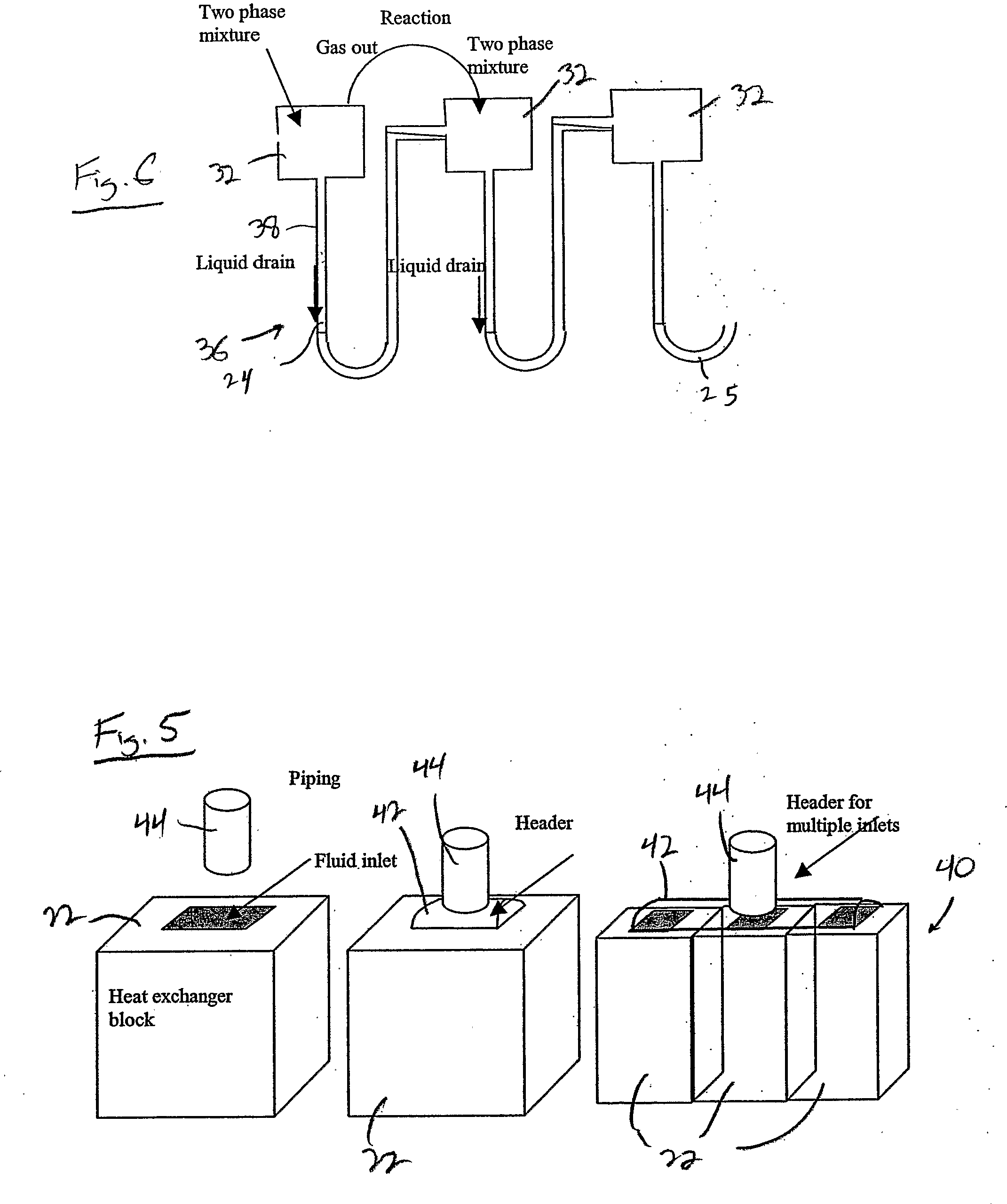
cascade reactor system can be achieved, and which is an integral part of the apparatus and method of the present invention, is the use of extended surface, or plate style heat exchangers in the
cascade reactor system. In particular, plate-fin (brazed or
diffusion bonded) or printed circuit heat exchangers (PCHE) are able to achieve
high effectiveness eliminating the requirement for multiple units for a single duty or a pre-heater to reduce the required effectiveness. The construction methods of plate style heat exchangers also allow for multiple
stream heat exchangers to be combined into a single unit. For example, the reactor outlet gases can pass through a
single plate style
heat exchanger where, in a first section, the gas is cooled with a high temperature
coolant such as pressurized water at 200-250 deg C. In a second section of the
heat exchanger, the reactor gases are cooled by
thermal contact with the reactor inlet stream. Finally, in a third section, the reactor gases are cooled with cooling water to condense the water.
[0032]When a series or
cascade of reactors is used, as discussed previously, the appropriate design for heat
recovery may differ as the reactor diminish in size. In the early reactors of the set the cost of heat recovery is more economical as the energy recovered per unit is greatest. With each successively smaller reactor and associated heat exchanger, the amount of energy that is available per unit diminishes as the rate of production of methanol in the set is smaller and the costs of heat recovery can become prohibitive. So, the present invention can utilize as the first reactor a steam raising or gas tube cooled reactor within a recycle loop, as discussed previously. The subsequent reactor sets each utilize a high efficiency heat exchanger of the aforementioned type integrating high grade heat recovery, feed
effluent heat exchange and methanol condensation utilizing cooling water, whereas the final reactor set only utilizes a high efficiency heat exchanger for feed /
effluent heat exchange and
water cooling.
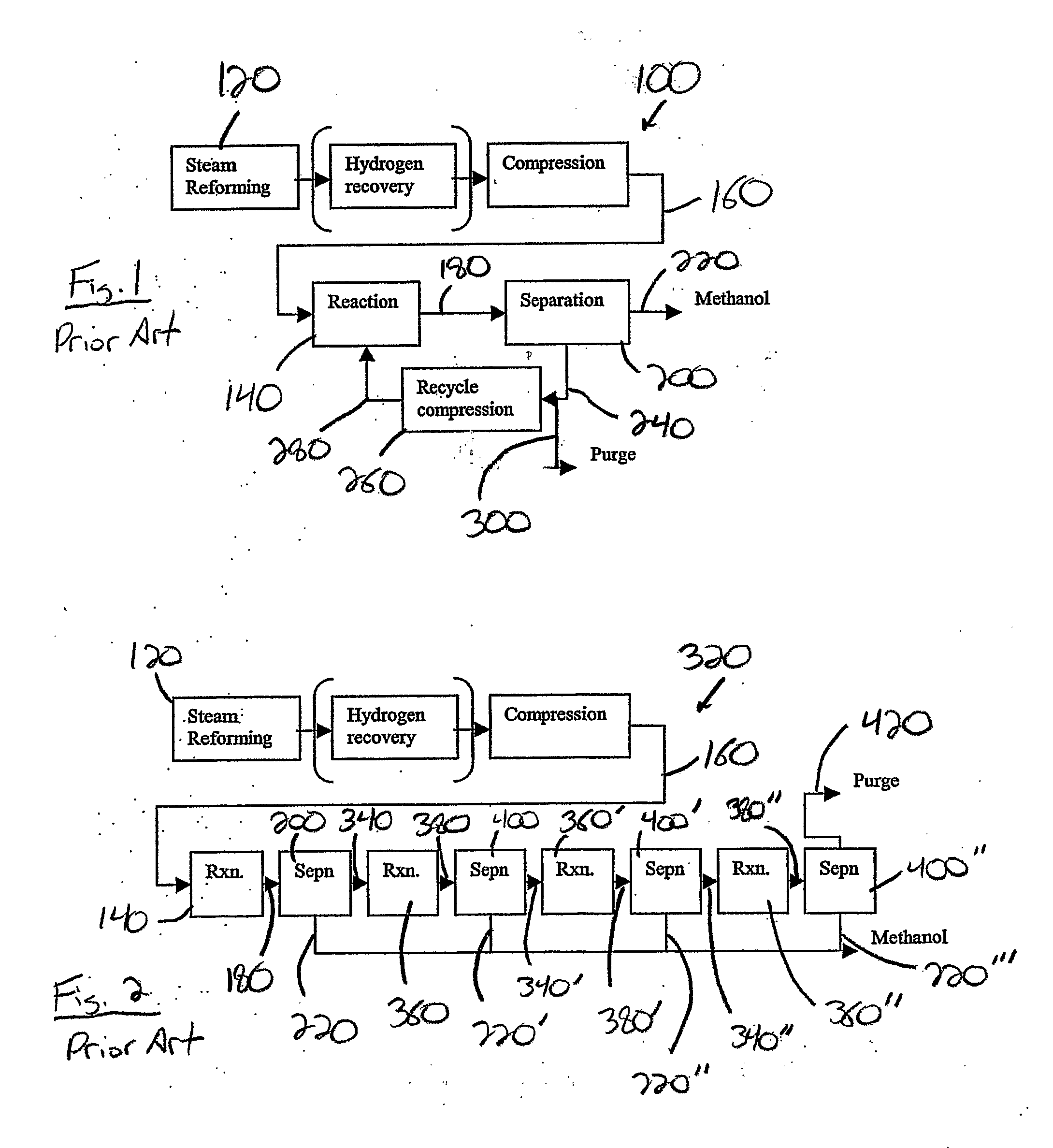
[0034]The integration of these units allows for several different uses of the integrated units. For example, a cascade reactor set unit of 3 or 4 reactors could be connected to the purge gas stream from a methanol synthesis loop to allow for the further reaction of the contents of the purge gas stream through the unit to form additional methanol. This would increase the overall conversion percentage of the loop without increasing the recycle rate, as only the purge gas is directed through the cascade reactor set unit. Also, the addition of the cascade reactor unit would both increase the amount of methanol that can be made from a fixed stream of
methane, or, as part of a wider retro-fit to an existing production process, would boost the capacity of the methanol synthesis section without an increased gas rate through the recycle compressor.
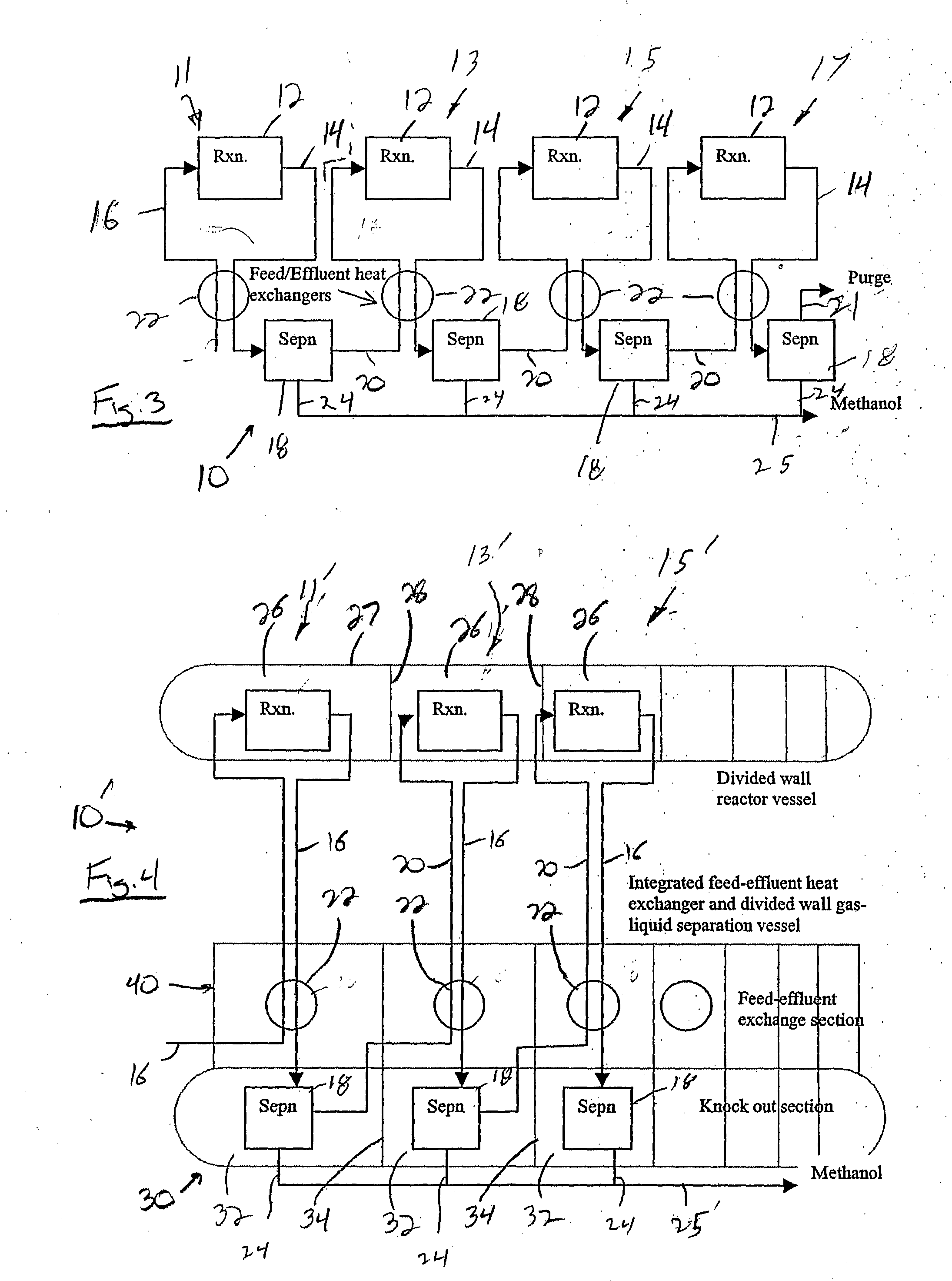
[0036]According to another aspect of the present invention, the various reactor sets of the cascade
system are formed as reaction zones integrated within a single reactor vessel, such that only the reactor vessel and appropriate inlet and outlet fittings on the vessel need to be constructed to withstand the temperatures and pressures necessary for the methanol production reaction. The reaction products from each
reaction zone are passed through the high-efficiency heat exchangers which are also formed in a block-like configuration positioned and connected between each
reaction zone in the reactor vessel, and a separator zone located in a separate separator vessel constructed similarly to the reactor vessel. The construction of the various reaction zones within the reactor vessel and the various separator zones within the separation vessel greatly reduces the cost of the materials necessary to construct the various vessels, as the pressure differentials between the respective zones in each of the reactor vessel and the separation vessel are minimal. This eliminates the need for constructing individual walls between the various zones of materials capable of withstanding the
high pressure differentials between reaction pressure and
atmospheric pressure that would otherwise be encountered.
[0037]According to still a further aspect of the present invention, an improved multiple or cascade reactor set type methanol production
system is provided in which methanol is initially produced through the use of any suitable methanol production
system, such as a conventional methanol synthesis loop with a recycle compressor. The purge gas stream from the methanol production system is subsequently directed through a cascade system of three or more reactor sets formed according to the present invention that further react the unreacted components of the purge gas stream to form additional methanol. The reactors are constructed separately, or as part of a
single vessel with a separating wall designed to contain the
differential pressure between the reactors and provide access between reactors to aid filling of the individual beds with catalyst. In each reactor set a single multi-stream heat exchanger is used to recover high grade heat, to effect feed /
effluent heat exchange, and to achieve condensation of methanol by further cooling with a
cooling medium such as water. In addition, the compact multi-stream heat exchangers are arranged in such a manner alongside the reactor set so as to minimize the amount of connections between the cascade reactor set and the synthesis loop.
[0038]According to still another aspect of the present invention, the multiple reactor set utilizing the high-efficiency plate-type or extended surface heat exchangers can be utilized as a stand-alone stationary or mobile system and / or as an add-on to an existing recycle loop reactor set or to an existing cascade reactor set to further increase the percent conversion of methanol from these pre-existing reactors, or maintain the overall conversion of the modified process while relaxing the effectiveness of the recycle process through, for example, a reduced recycle rate.
