
Apparatus for Producing Synthesis Gas

a technology of apparatus and synthesis gas, which is applied in the direction of chemical apparatus and processes, inorganic chemistry, chemical/physical/physicochemical processes, etc., can solve the problems of difficult making and installation, substantial restrictions on the operation of the above apparatuses, and laborious installation of such refractory linings, etc., to avoid thermal stress in the ceramic pipe, low mass, and low mechanical resistance

Inactive Publication Date: 2009-09-03
CASALE CHEM SA
View PDF6 Cites 2 Cited by
  • Summary
  • Abstract
  • Description
  • Claims
  • Application Information

AI Technical Summary

Benefits of technology

[0024]Moreover, it should be noted that the ceramic material of the pipe intrinsically has a high capability to resist much greater thermal shocks than those that can be withstood by conventional refractory materials thanks to its low thickness and high thermal conductivity allowing the temperature gradients in the ceramic pipe to be considerably reduced, thus minimising the thermal stresses.
[0039]In order to reduce the passage of gas, from the reaction chamber towards the insulating filling, through the intrinsic pores of the ceramic material, the inner surface of the ceramic pipe can be subjected to a vitrification process to eliminate surface porosity.

Problems solved by technology

Moreover, the installation of such refractory linings is very laborious requiring very long time periods and highly specialised personnel since it is necessary to arrange the bricks or cement casts in such a way to avoid the formation of channels or slits allowing the diffusion of heat and gas towards the shell.
As well as being difficult to make and install, conventional refractory linings impose substantial restrictions upon the operation of the aforementioned apparatuses.
At first, after installation, a long time is needed for curing, drying and sintering of the refractory lining.
In fact, the exceeding of the maximum thermal gradient can often lead to ruinous damages to the refractory lining itself.
For these reasons, the heating and cooling steps of the aforementioned apparatuses can require a number of days.

Method used


Image

  • Apparatus for Producing Synthesis Gas
  • Apparatus for Producing Synthesis Gas
  • Apparatus for Producing Synthesis Gas

Examples


Embodiment Construction

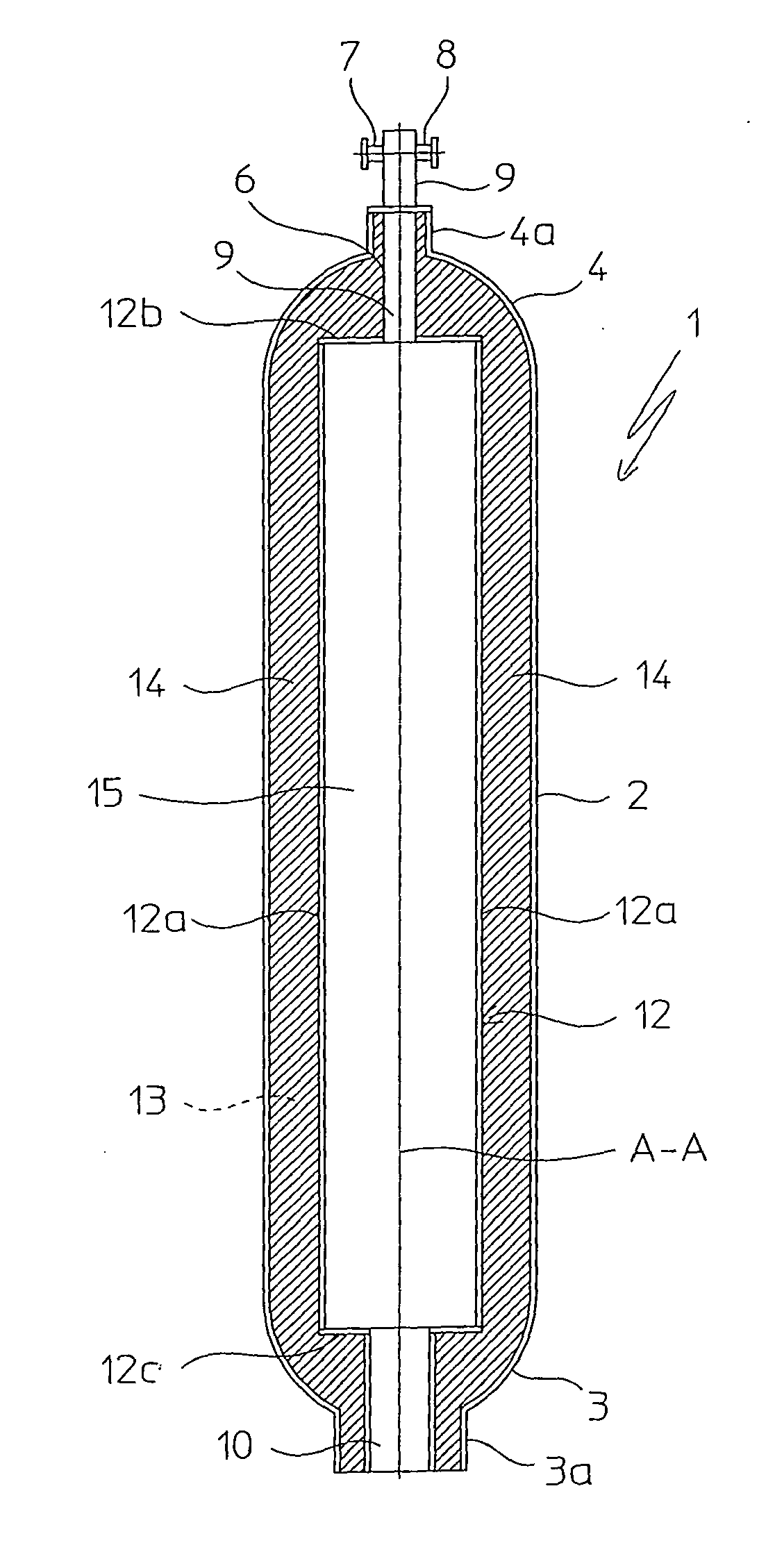
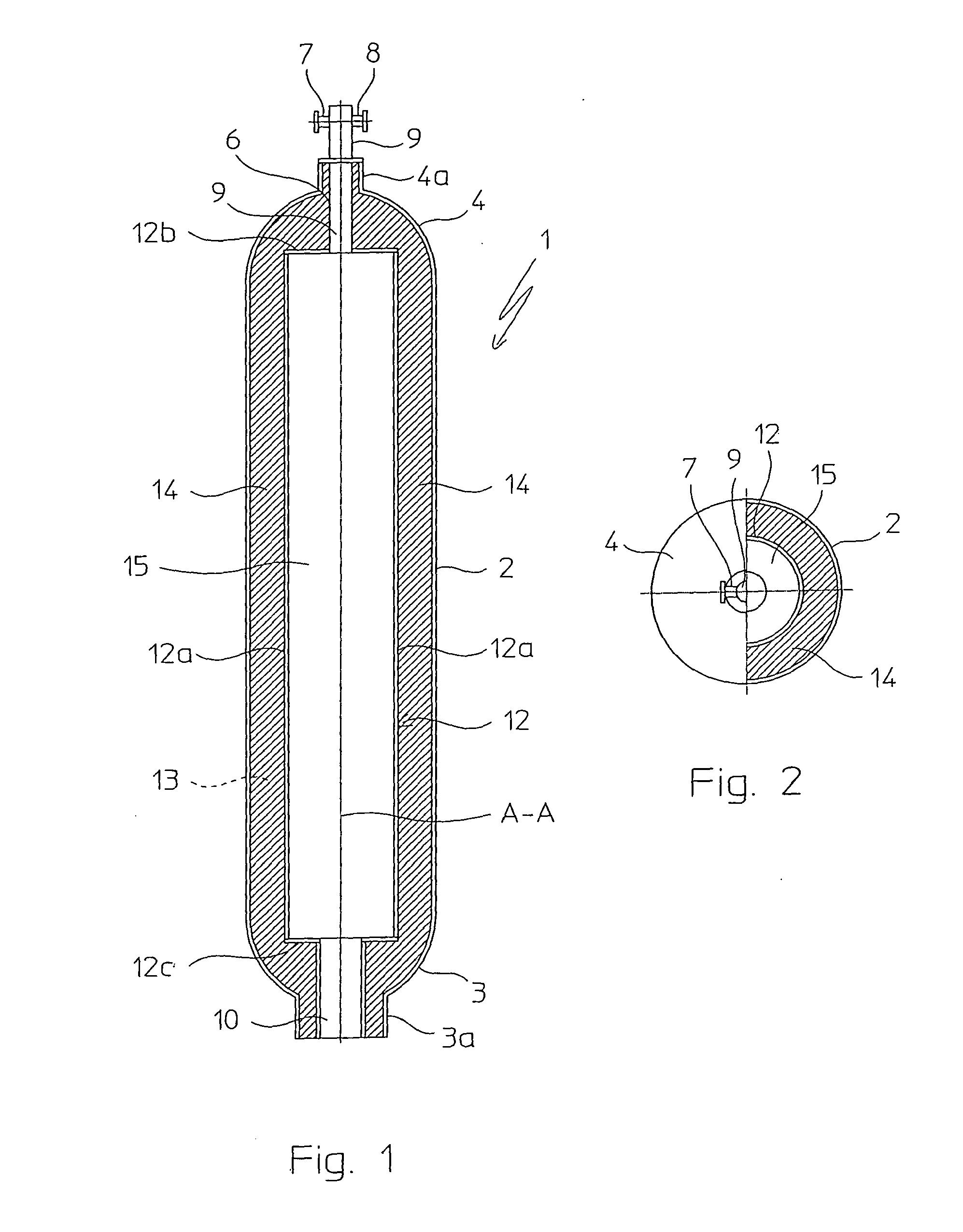
[0045]With reference to FIGS. 1 and 2, an apparatus according to the invention for producing synthesis gas is globally indicated with 1.

[0046]The apparatus 1 can be used particularly for partial oxidation and / or reforming of hydrocarbons in the absence of catalyst and it is particularly suitable for producing synthesis gas for methanol, ammonia or other chemicals.

[0047]The apparatus 1 generally operates at temperatures of between 800-1700° C. and pressures of between 5-200 bar.

[0048]The apparatus 1 comprises a substantially cylindrical shell 2 with vertical axis A-A closed at the opposite ends by respective lower bottom 3 and upper bottom 4. The upper bottom 4 is provided with a nozzle 4a having an opening for the insertion, in a suitable housing 6, of a per se conventional burner, globally indicated with 9. The body of the burner 9 projects from said nozzle 4a towards the outside of the shell 2 and ends at the top with a nozzle 7 constituting an opening for the entry of a gaseous f...


PUM


Abstract

An apparatus (1) for producing synthesis gas is described, the apparatus comprising a substantially cylindrical shell (2) closed by opposite bottoms (3,4), at least one inlet opening (8) for feeding a gaseous flow comprising oxygen, at least one inlet opening (7) for a gaseous flow comprising hydrocarbons and at least one outlet opening for a flow of synthesis gas and at least one burner (9) in fluid communication with a reaction chamber (15) for partially oxidising and / or reforming said hydrocarbons obtaining said flow of synthesis gas, and being characterised in that it comprises a pipe (12) of a ceramic material extended inside said shell (2), said pipe (12) of ceramic material internally defining said reaction chamber (15).

Description

FIELD OF APPLICATION[0001]In its most general aspect, the present invention concerns an apparatus for producing gaseous mixtures comprising hydrogen, carbon monoxide and optionally nitrogen such as synthesis gases for methanol and ammonia.[0002]In particular, the present invention concerns an apparatus of the aforementioned type comprising a substantially cylindrical shell closed at opposite ends, at least one inlet opening for feeding a gaseous flow comprising oxygen, at least one inlet opening for feeding a gaseous flow comprising hydrocarbons, at least one outlet opening for a flow of synthesis gas, at least one burner in fluid communication with a reaction chamber for carrying out reforming reactions of the hydrocarbons and / or for partially oxidising said hydrocarbons obtaining said flow of synthesis gas, said reaction chamber being in fluid communication with said at least one outlet opening and optionally containing a suitable catalytic bed to promote said reforming reactions....

Claims


Application Information

Patent Timeline
Patent Type & Authority Applications(United States)
IPC IPC(8): B01J19/02
CPCB01J8/025C01B3/24B01J2208/00495B01J2208/00504B01J2219/00155B01J2219/00157B01J2219/0218B01J2219/0263C01B3/34C01B3/36C01B3/382C01B2203/0216C01B2203/0222C01B2203/0244C01B2203/0255C01B2203/061C01B2203/068C01B2203/0811C01B2203/0844C01B2203/142C01B2203/82B01J7/00B01J8/0285
Inventor ZANICHELLI, LUCAFERRINI, CRISTINA
Owner CASALE CHEM SA
Learn More