
Electrophoretic display device and electronic apparatus

Inactive Publication Date: 2009-08-27
SEIKO EPSON CORP
View PDF4 Cites 3 Cited by
  • Summary
  • Abstract
  • Description
  • Claims
  • Application Information

AI Technical Summary

Benefits of technology

[0009]An advantage of some aspects of the invention is that it provides an electrophoretic display device in which a flow of a leakage current between pixels is suppressed to improve the reliability of a resulting product. Another advantage of some aspects of the invention is that it provides an electronic apparatus including the electrophoretic display device.
[0011]In the electrophoretic display device, the insulating layer disposed between the pixel electrodes blocks a flow of a leakage current, that is, a lateral electric field, between the adjacent pixel electrodes. Consequently, the occurrence of the leakage current between the pixels can be suppressed. The insulating layer is made of a hygroscopic insulating material. Therefore, for example, when an electrophoretic display device has an adhesive layer between the pixel electrodes and the electrophoretic layer, moisture contained in the adhesive layer is absorbed by the insulating layer and is thereby removed from the adhesive layer. Accordingly, the occurrence of a leakage current caused by moisture is prevented to suppress the leakage current itself. Consequently, a decrease in display performance and an increase in consumption current caused by leakage current are inhibited, resulting in an improvement in reliability of a resulting product.
[0013]The insulating layer absorbs moisture, and, thereby, the insulation quality of the insulating layer may be locally decreased due to this absorbed moisture. However, since the insulating layer is spaced from the pixel electrodes, for example, an adhesive layer can be disposed between the adjacent pixel electrodes. Thus, the pixel electrodes do not adjoin to each other with only the insulating layer absorbing moisture therebetween. Consequently, the leakage current due to moisture absorbed by the insulating layer is reliably prevented from flowing between the adjacent pixel electrodes.
[0015]In such a structure, the leakage current has to cross over the upside of the insulating layer between the adjacent pixel electrodes. Therefore, the path of the leakage current becomes long (large), which prevents the leakage current from flowing between the pixel electrodes.
[0019]Since the electronic apparatus is provided with the electrophoretic display device that is prevented from a decrease in display performance and an increase in power consumption caused by leakage current and is thereby improved in reliability, the electronic apparatus itself is satisfactorily improved in reliability.

Problems solved by technology

This generates a large difference in electric potential between the adjacent pixel electrodes, resulting in a flow of a leakage current between the adjacent pixel electrodes through moisture and other substances in an adhesive layer disposed on the pixel electrode.
Although the leakage current per pixel is small, the total leakage current over the entire display unit of the electrophoretic display device becomes large.
This leads to an increase in power consumption.
In addition, inverted display area is enlarged to complicate the display.
This also leads to an increase in power consumption.
Furthermore, the leakage current may cause a chemical reaction in the pixel electrodes, resulting in a decrease in reliability of the electrophoretic display device, in particular, when the display device is used for a long time.
Consequently, a decrease in display performance and an increase in consumption current caused by leakage current are inhibited, resulting in an improvement in reliability of a resulting product.

Method used


Image

  • Electrophoretic display device and electronic apparatus
  • Electrophoretic display device and electronic apparatus
  • Electrophoretic display device and electronic apparatus

Examples


modification example

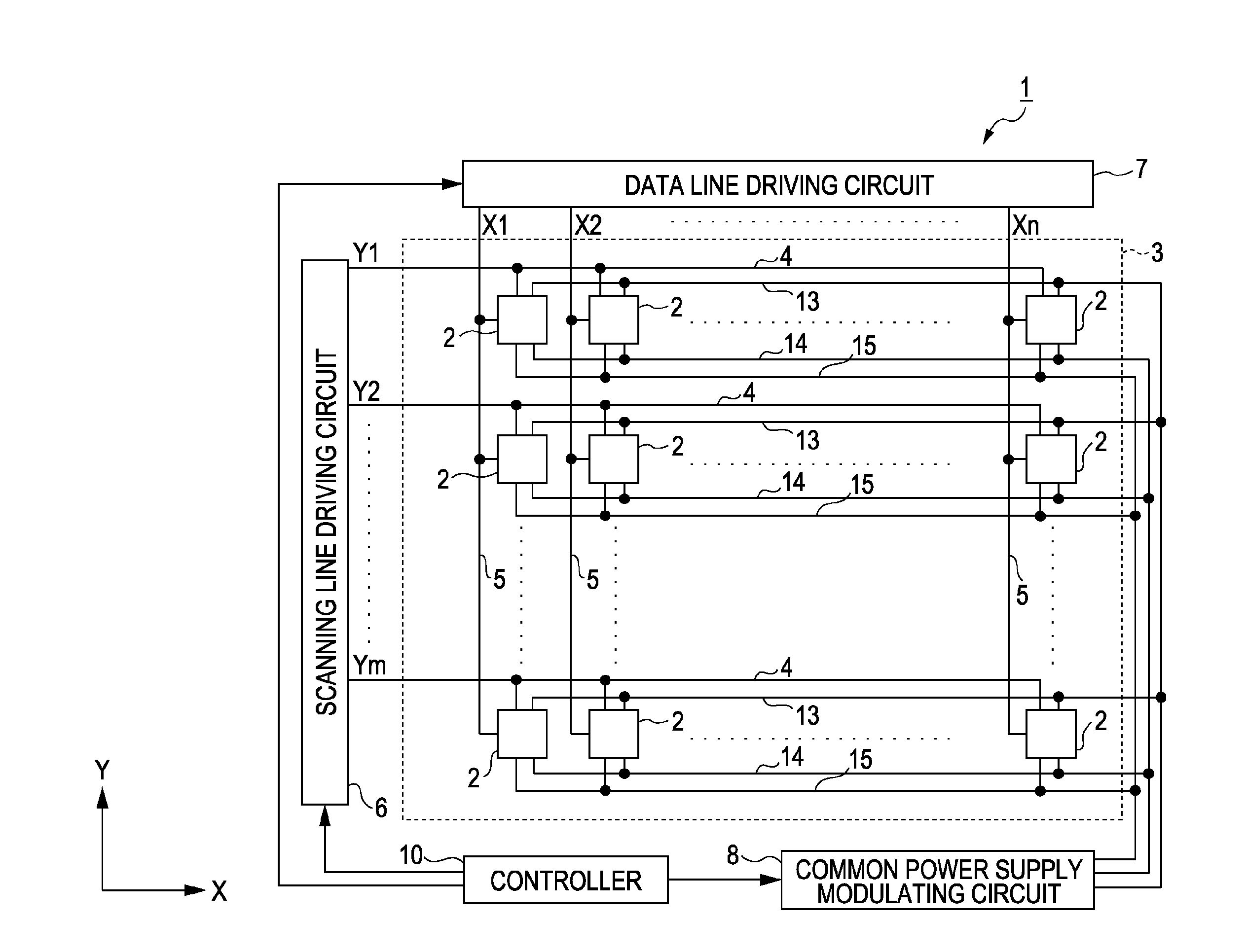
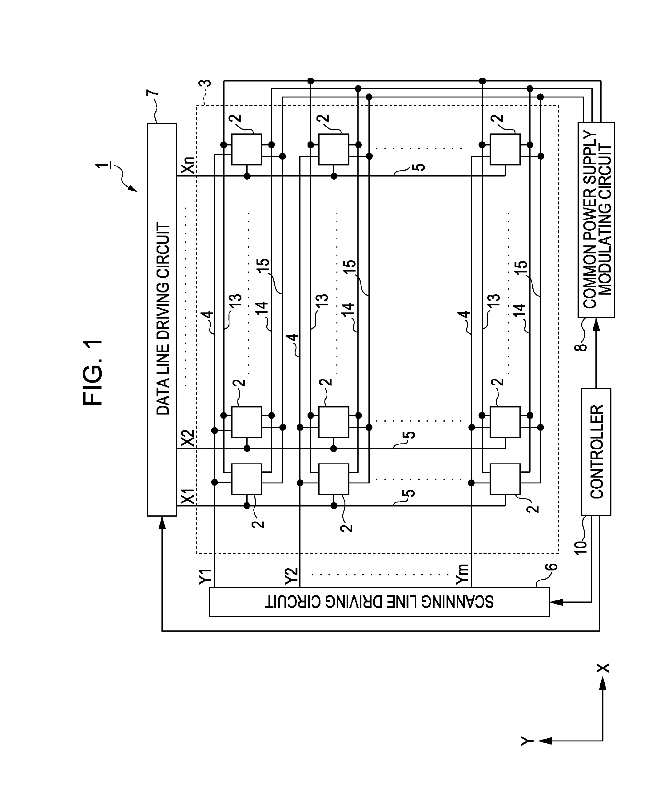
[0098]FIG. 10 is a configuration diagram of the electrophoretic display device 101 according to an aspect of the invention. The circuit configuration of this electrophoretic display device 101 is different from that of the electrophoretic display device1 in that the common power supply-modulating circuit 108 is connected to pixels 102 via a first controlling line 111 and a second controlling line 112.

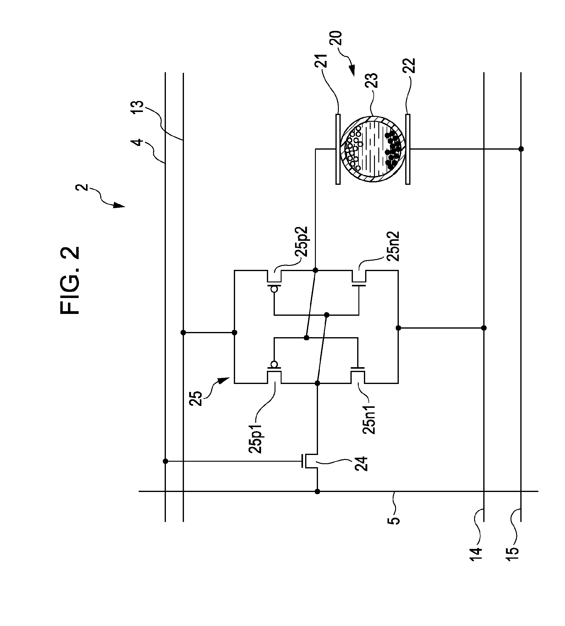
[0099]FIG. 11 is a circuit diagram of a pixel 102. The pixel 102 includes a switching circuit 135 disposed between an SRAM 25 and a first electrode 21. The switching circuit 135 includes a first transfer gate 136 and a second transfer gate 137. The transfer gates 136 and 137 are composed of a P-MOS and an N-MOS connected in parallel.

[0100]The gate portions of the transfer gates 136 and 137 are connected to the SRAM 25. The source side of the first transfer gate 136 is connected to the first controlling line 111. The source side of the second transfer gate 137 is connected to the second ...


PUM


Abstract

An electrophoretic display device includes pixels planarly arranged and including electrophoretic devices. The electrophoretic devices each include a pixel electrode, an opposite electrode opposing the pixel electrode, and an electrophoretic layer disposed between the pixel electrode and the opposite electrode and including electrophoretic particles. The region between the pixel electrodes adjacent to each other is provided with an insulating layer including a hygroscopic insulating material.

Description

BACKGROUND[0001]1. Technical Field[0002]The present invention relates to an electrophoretic display device and an electronic apparatus.[0003]2. Related Art[0004]Electrophoretic display devices, which have electrophoretic dispersions each containing a liquid phase dispersing medium and electrophoretic particles and utilize a change in optical characteristics of the electrophoretic dispersion due to a change in distribution of the electrophoretic particles when an electric field is applied thereto, are known. The electrophoretic display devices do not require backlights and, therefore, can be reduced in cost and thickness. Furthermore, since the electrophoretic display devices achieve wide viewing angles and high contrast ratios and are also memory displays, they are expected as a next-generation display device.[0005]In order to display an image with such an electrophoretic display device, an image signal is once stored in a memory circuit through a switching element. The image signal...

Claims


Application Information

Patent Timeline
IPC IPC(8): G09G3/34G02F1/167G02F1/16756G02F1/16757
CPCG02F1/167G02F2201/50G02F2001/133337G02F1/16757G02F1/16756G02F1/133337
Inventor AMANO, TAKAHIRO
Owner SEIKO EPSON CORP
Learn More