
Correction of TFT non-uniformity in amoled display

a technology of amoled display and non-uniformity, which is applied in the direction of static indicating devices, instruments, etc., can solve the problems of low accuracy, low accuracy, and limited number of lines of current-sourced drive electronics

Inactive Publication Date: 2009-08-27
SILICONFILE TECH INC
View PDF9 Cites 56 Cited by
  • Summary
  • Abstract
  • Description
  • Claims
  • Application Information

AI Technical Summary

Benefits of technology

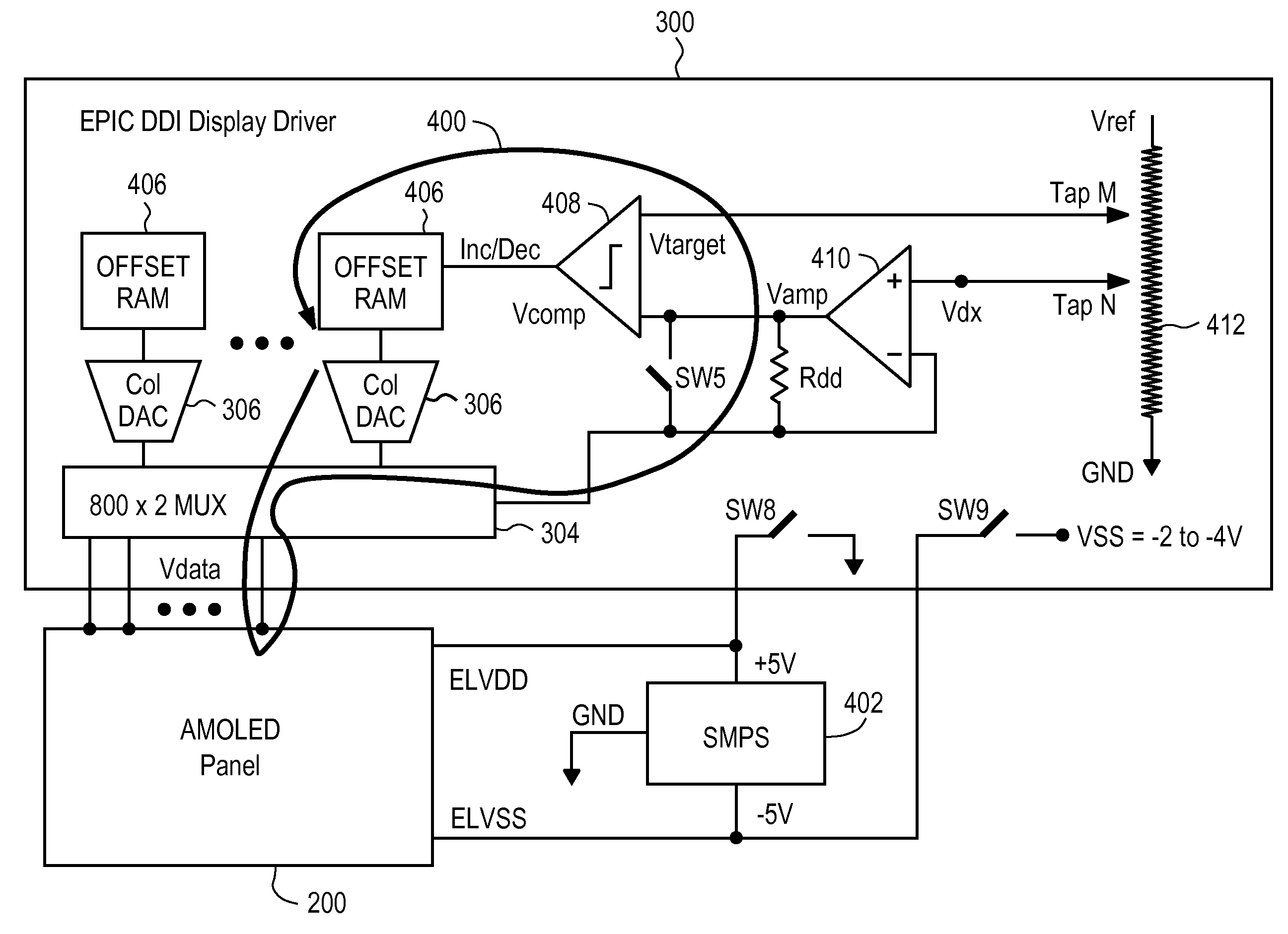
"The present invention relates to a method for correcting Mura (distortion) in AMOLED displays by forced convergence of sub-pixel current to a desired level regardless of the source of pixel current error. This is achieved by using a feedback control circuit to force the pixel transistor current of each sub-pixel to match a predetermined target current. The feedback control circuit can be a single-sided or differential transresistance amplifier. The method allows for accurate Mura calibration and correction of streaking or spotting in the display."

Problems solved by technology

While PM OLEDs are fairly simple structures to design and fabricate, they demand relatively expensive, current-sourced drive electronics to operate effectively and are limited as to the number of lines because only one line can be on at a time and therefore the PM OLED must have instantaneous brightness equal to the desired average brightness times the number of lines.
Thus, PM OLED displays are typically limited to under 100 lines.
In addition, their power consumption is significantly higher than that required by an active-matrix OLED.
However, the TFTs in the AMOLED are typically fabricated with poly-silicon (p-Si) that is difficult to fabricate in a uniform manner.
Unfortunately the grain size produced in the laser anneal step is not uniform due to a temperature spread in the laser beam.
Thus, uniform TFTs are very difficult to produce and thus the current supplied by TFTs in conventional AMOLED displays is often non-uniform, resulting in non-uniform display brightness.
In other words, TFTs may produce different OLED currents due to their non-uniformities from pixel to pixel, even if the same gate voltage is applied to the TFTs.
Another problem with AMOLED displays occurs due to aging of the material in the OLEDs.
As the OLED diode in each sub-pixel ages with use, it becomes less efficient in converting current to light, i.e., the efficiency of light emission of the OLED diode decreases.
In addition, since the OLED diodes on various parts of the AMOLED display do not age (are not used) equally in a uniform manner, OLED aging also causes non-uniformity in the OLED display.

Method used


Image

  • Correction of TFT non-uniformity in amoled display
  • Correction of TFT non-uniformity in amoled display
  • Correction of TFT non-uniformity in amoled display

Examples


Embodiment Construction

[0024]The Figures and the following description relate to preferred embodiments of the present invention by way of illustration only. It should be noted that from the following discussion, alternative embodiments of the structures and methods disclosed herein will be readily recognized as viable alternatives that may be employed without departing from the principles of the claimed invention.

[0025]Reference will now be made in detail to several embodiments of the present invention(s), examples of which are illustrated in the accompanying figures. It is noted that wherever practicable similar or like reference numbers may be used in the figures and may indicate similar or like functionality. The figures depict embodiments of the present invention for purposes of illustration only. One skilled in the art will readily recognize from the following description that alternative embodiments of the structures and methods illustrated herein may be employed without departing from the principle...


PUM


Abstract

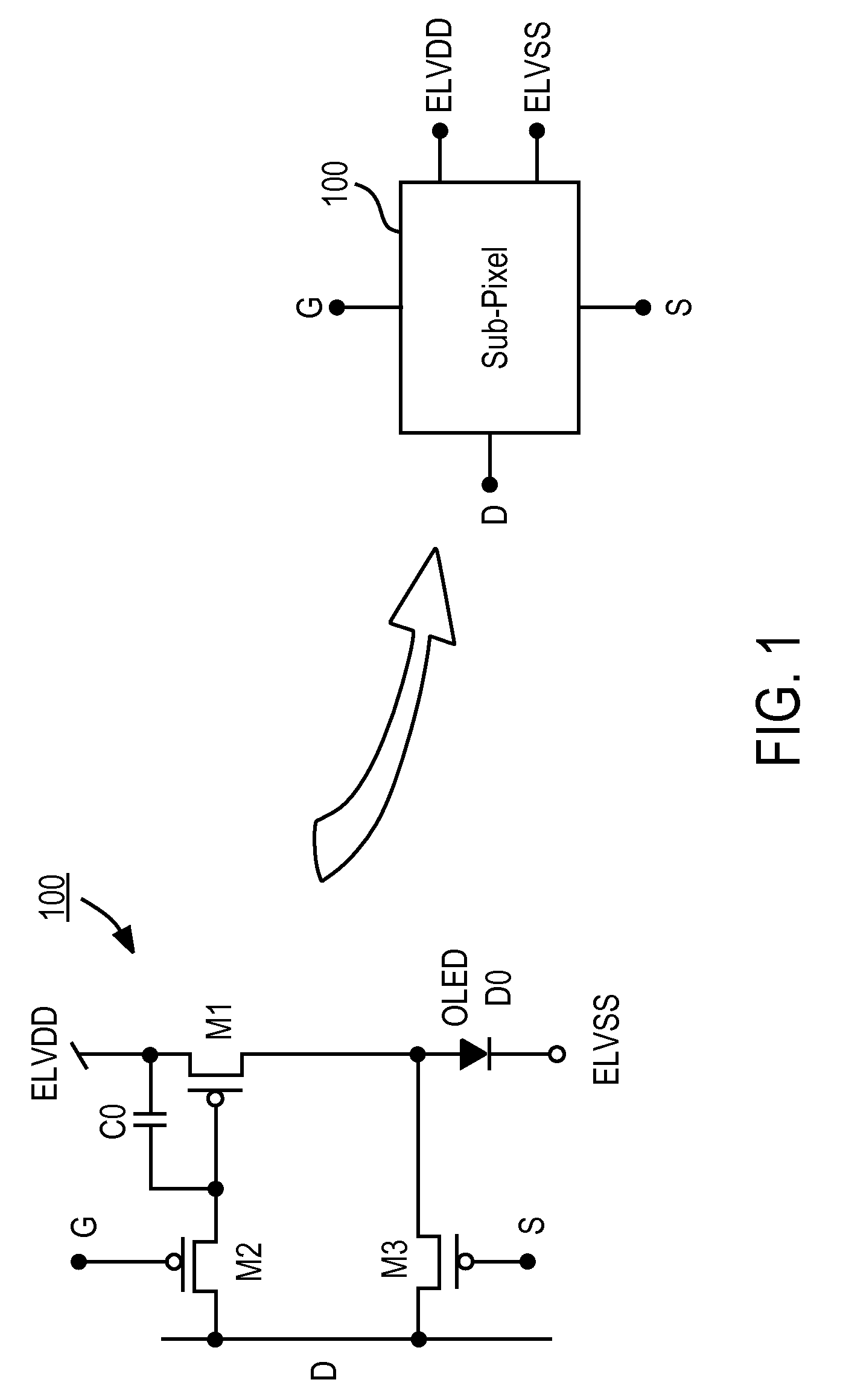
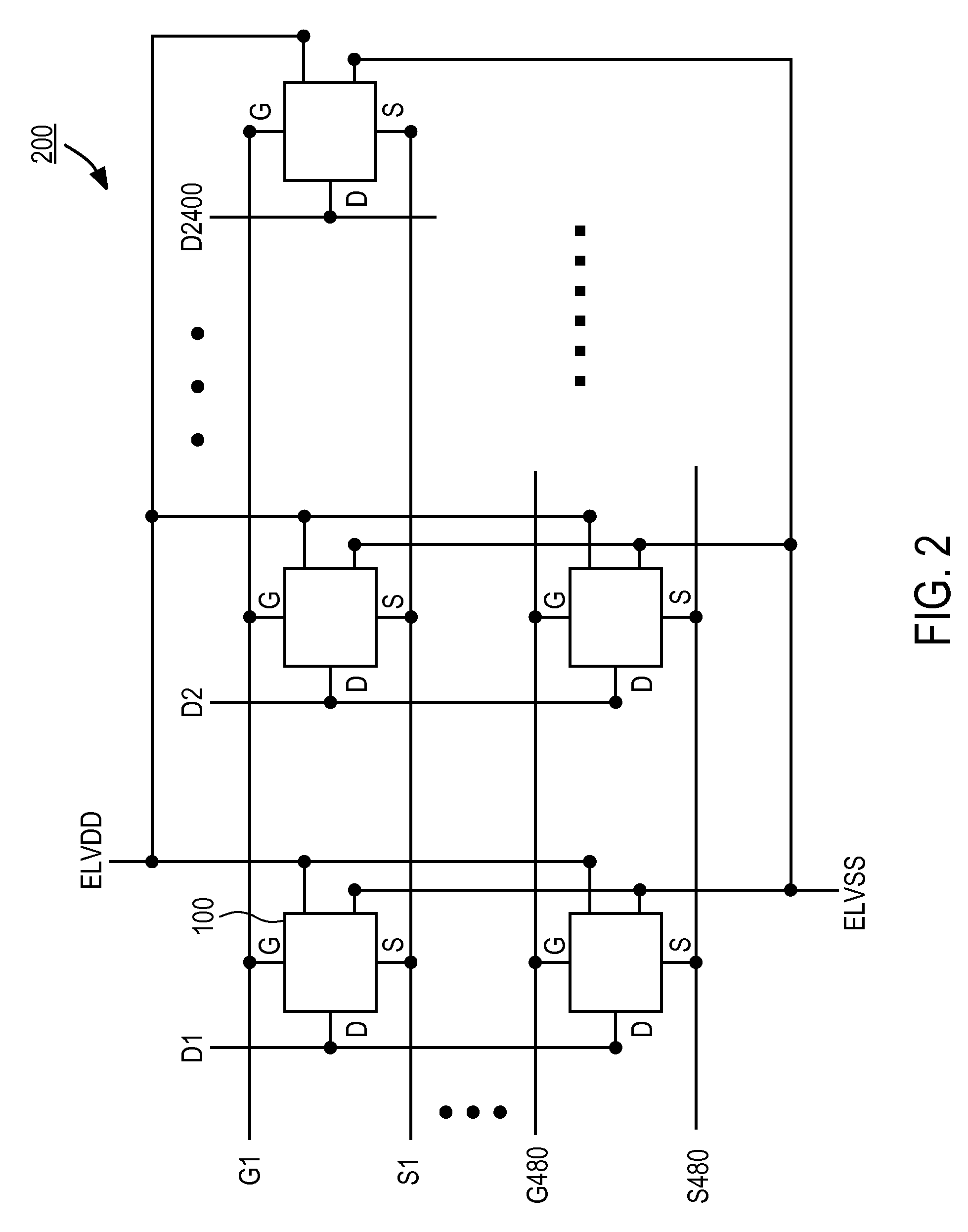
Sub-pixel current in an OLED display is forced to converge to a desired level regardless of the source of pixel current error. By using a feedback loop, the pixel transistor current is forced to be equal to a predetermined target current that is established by an analog control circuit. The predetermined target current is selected to generate the desired pixel transistor current through the sub-pixel, and can be set by setting a target voltage. The sub-pixels have a 3T cell structure including 3 TFTs, one TFT for connecting the data line to the storage capacitor, another TFT for driving the sub-pixel current, and still another TFT for connecting the OLED diode anode to the data line of the AMOLED panel. Thus, the feedback loop of the present invention (comprising Taps M and N of a resistor string, and an amplifier, a comparator, and digital logic) senses the pixel transistor current via the data lines of the AMOLED panel to compensate for Mura

Description

CROSS-REFERENCE TO RELATED APPLICATIONS[0001]The present invention claim priority under 35 U.S.C. §119(e) from U.S. Provisional Patent Application No. 61 / 031,220, entitled “Dynamic Calibration of Pixel Current Variation and Aging in AMOLED Display,” filed on Feb. 25, 2008, and from U.S. Provisional Patent Application No. 61 / 104,983, entitled “Correction of TFT Non-Uniformity in AMOLED Display,” filed on Oct. 13, 2008, the subject matters of both of which are incorporated by reference herein in their entirety.BACKGROUND OF THE INVENTION[0002]1. Field of the Invention[0003]The present invention relates to calibration of current variations in the pixels / sub-pixels of an active matrix organic light-emitting diode (AMOLED) display caused by non-uniformity of thin-film transistors (TFTs) in the sub-pixels.[0004]2. Description of the Related Arts[0005]An OLED display is generally comprised of an array of organic light emitting diodes (hereafter referred to as “OLED diodes”) that have carbo...

Claims


Application Information

Patent Timeline
Patent Type & Authority Applications(United States)
IPC IPC(8): G09G3/32
CPCG09G3/3233G09G3/3291G09G2300/0819G09G2300/0861G09G2320/0693G09G2320/0295G09G2320/043G09G2320/045G09G2320/0285
Inventor MCCREARY, JAMES LEO
Owner SILICONFILE TECH INC
Learn More