


Quick Research
Generate reliable direction feasibility study reports for your R&D in just a few steps.

Technical Q&A
Discover and master advanced knowledge NOW. Basics, ideas, possibilities, all at once.

Find Solutions
As an expert in R&D theories, this can generate solutions to your technical problems instantly.

Evaluate Feasibility
Analyze your overall solution with one click, know your potential R&D risks in advance.

Monitor Landscape
Get weekly tech updates, stay abreast of the latest tech innovations and key insights.
Polymer electrolyte fuel cell and fuel cell system including the same
a fuel cell and electrolyte technology, applied in the field of polymer electrolyte fuel cell and fuel cell system, can solve the problems of cell performance deterioration, and achieve the effect of avoiding the deterioration of cell performan
- Summary
- Abstract
- Description
- Claims
- Application Information
AI Technical Summary
Benefits of technology
Problems solved by technology
Method used
Image

Examples
embodiment 1
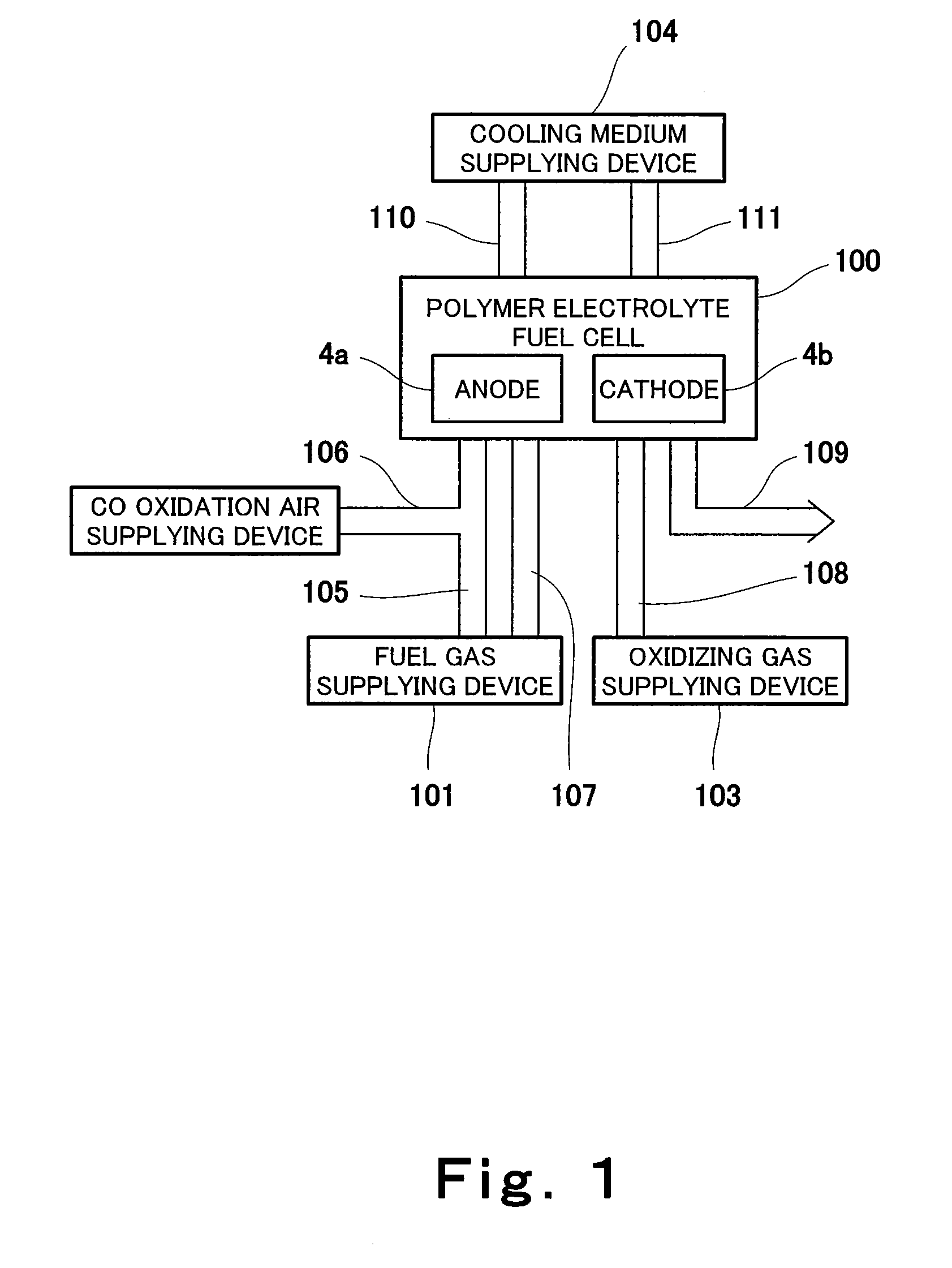
[0095]FIG. 1 is a block diagram schematically showing the configuration of a fuel cell system according to Embodiment 1 of the present invention.
[0096]First, the configuration of the fuel cell system according to Embodiment 1 will be explained.
[0097]As shown in FIG. 1, the fuel cell system according to Embodiment 1 includes a polymer electrolyte fuel cell (hereinafter referred to as “PEFC”) 100, a fuel gas supplying device 101, a fuel gas supplying passage 105, a CO oxidation air supplying device 102, an air supplying passage 106, a fuel gas discharging passage 107, an oxidizing gas supplying device 103, an oxidizing gas supplying passage 108, an oxidizing gas discharging passage 109, a heat transfer medium supplying device 104, a heat transfer medium supplying passage 110, and a heat transfer medium discharging passage 111.
[0098]The PEFC 100 is connected to the fuel gas supplying passage 105, and the fuel gas supplying passage 105 is connected to the fuel gas supplying device 101. ...
embodiment 2
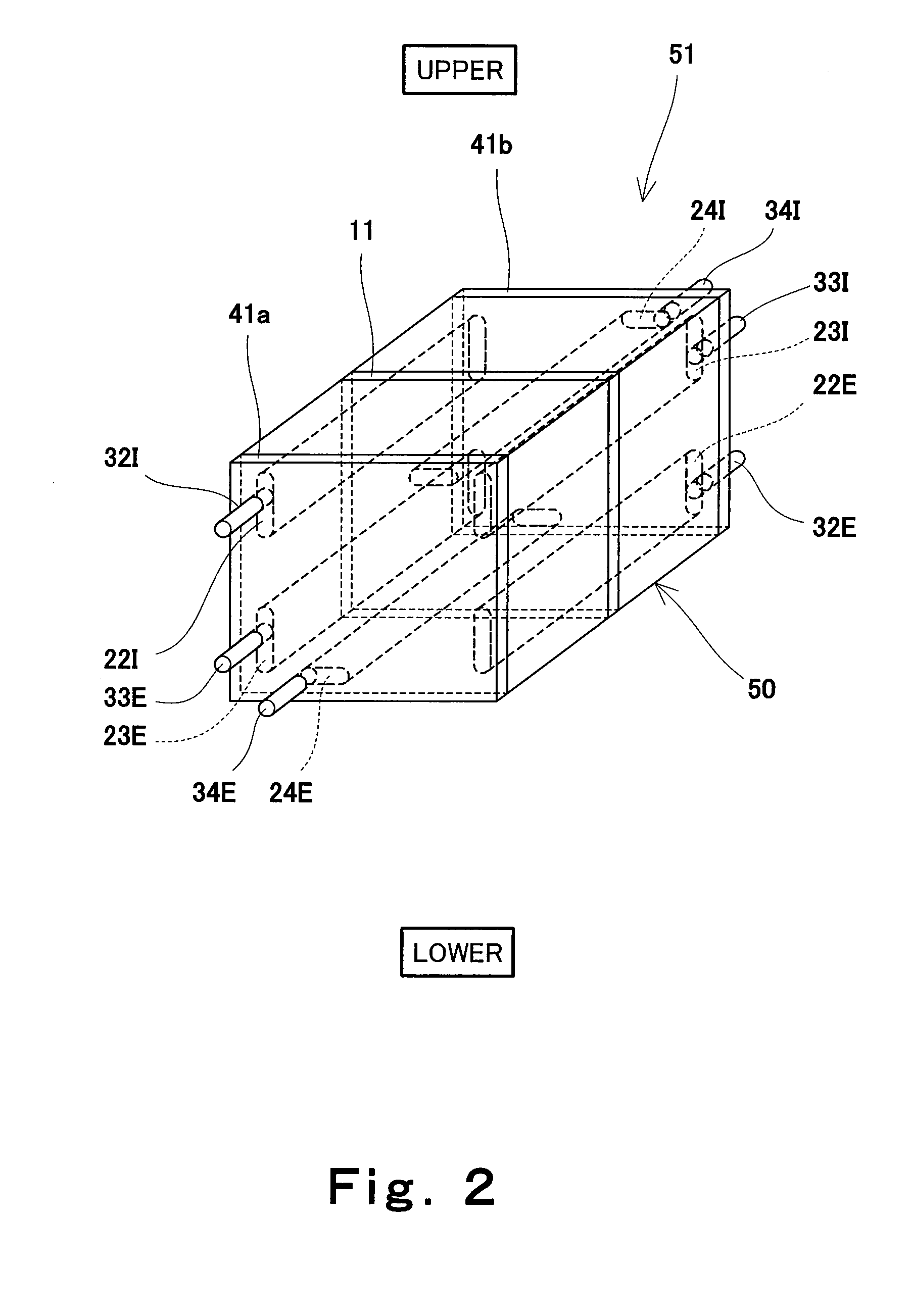
[0135]FIG. 5(a) is a schematic diagram showing a part of the configuration of a PEFC 100a of the fuel cell system according to Embodiment 2 of the present invention. FIGS. 5(b) and 7 are schematic diagrams showing a part of the cross section of the PEFC 100a shown in FIG. 5(a).
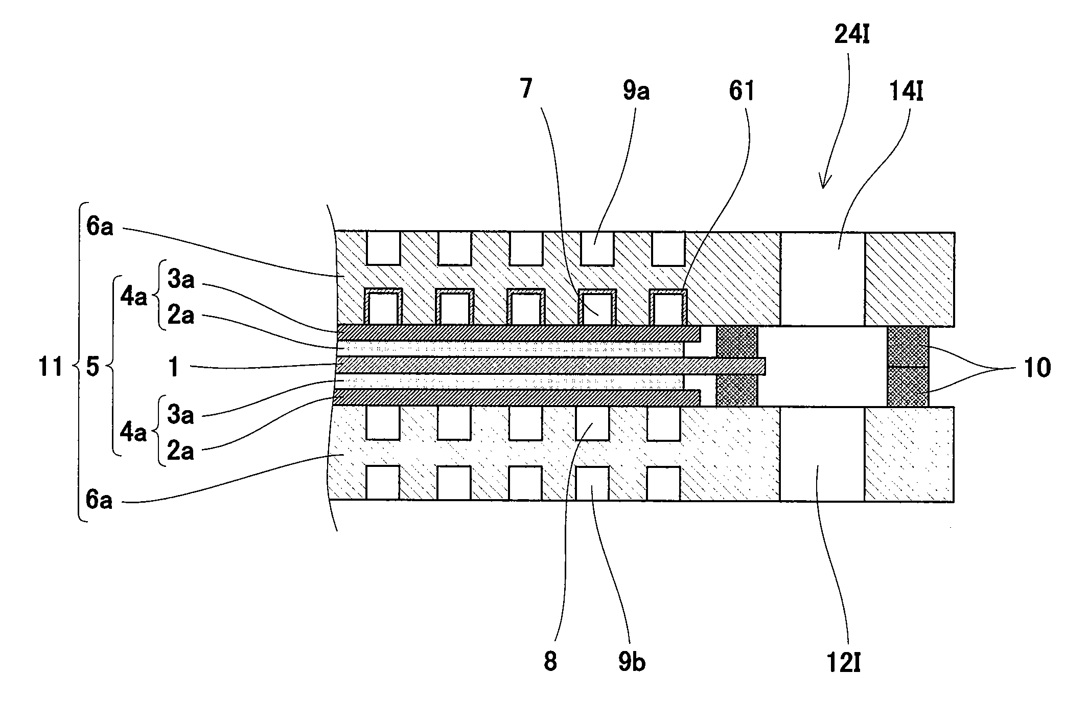
[0136]As shown in FIGS. 5(a), 5(b) and 7, in the PEFC 100a of the fuel cell system according to Embodiment 2, a CO remover 64 is fittingly inserted in the anode gas supplying manifold 22I. The CO remover 64 includes a tubular container 62 and a columnar carrier 63 which is fittingly inserted in the container 62 and supports the CO removing catalyst. The container 62 is disposed such that one side surface (end portion) thereof contacts a main surface of the first end plate 41a (to be specific, the current collector, not shown), and a predetermined gap is formed between the other side surface (end portion) thereof and a main surface of the second end plate 41b (to be specific, the current collector, not shown) (...
modification example 1
[0143]FIG. 6 is a schematic diagram showing the configuration of a CO remover 64a of Modification Example 1 of Embodiment 2.
[0144]As shown in FIG. 6, in Modification Example 1, pellet-form carriers 63a supporting the CO removing catalyst are filled in the internal space of the container 62 such that gaps remain in the internal space of the container 62. The carrier 64 has such a size that it does not flow into the anode gas channel 7, and its shape is not limited. Herein, the pellet-form carrier 63a is used, but the present modification example is not limited to this. For example, plate-like carriers may be stacked in the internal space of the container 62 such that gaps remain in the internal space of the container 62. Moreover, the pellet-form carrier 63a may be constituted by a porous body having a large number of fine holes, and the CO removing catalyst may be supported by an inner surface of the fine hole.
[0145]With this configuration, in the fuel cell system of the present mod...
PUM
 Abstract
Description
Claims
Application Information
 - R&D Engineer
- R&D Manager
- IP Professional
- Industry Leading Data Capabilities
- Powerful AI technology
- Patent DNA Extraction
Browse by: Latest US Patents, China's latest patents, Technical Efficacy Thesaurus, Application Domain, Technology Topic, Popular Technical Reports.
© 2024 PatSnap. All rights reserved.Legal|Privacy policy|Modern Slavery Act Transparency Statement|Sitemap|About US| Contact US: help@patsnap.com