
Surveillance and warning system

a technology applied in the field of surveillance and warning system, can solve the problems of inability to meet the needs of an operational system, inability to provide a flexible and scalable system or method for collecting data from a variety of sensor components and communicating that information to an intelligent (i.e., rule-based) communication network

Inactive Publication Date: 2009-08-13
PATRIOT TECH
View PDF12 Cites 100 Cited by
  • Summary
  • Abstract
  • Description
  • Claims
  • Application Information

AI Technical Summary

Benefits of technology

[0031]Preferably, the CSP is built around a high reliability single board computer (SBC) that executes software under an embedded operating system, preferably LINUX, which continually processes all detection and surveillance data to derive and catalog perimeter data patterns, thereby building a dynamic model of the ambient environment. Through this continuous refinement, the system according to the invention will reduce the number of false alerts and alarms.
[0067]Another object of an embodiment of the system and method of the present invention is to facilitate rapid deployment for system evaluation or temporary operations, or to coordinate installation construction schedules by having the ROWS™ system design accommodate the use of COTS spread-spectrum RF communications links.

Problems solved by technology

Light control timing was seen to be adequate for the proof-of-concept demonstration, but suffered minor deficiencies that would not be acceptable in an operational system.
Also available are the more complex and expensive technologies, including electronic-field and capacitance-discharge sensor technologies.
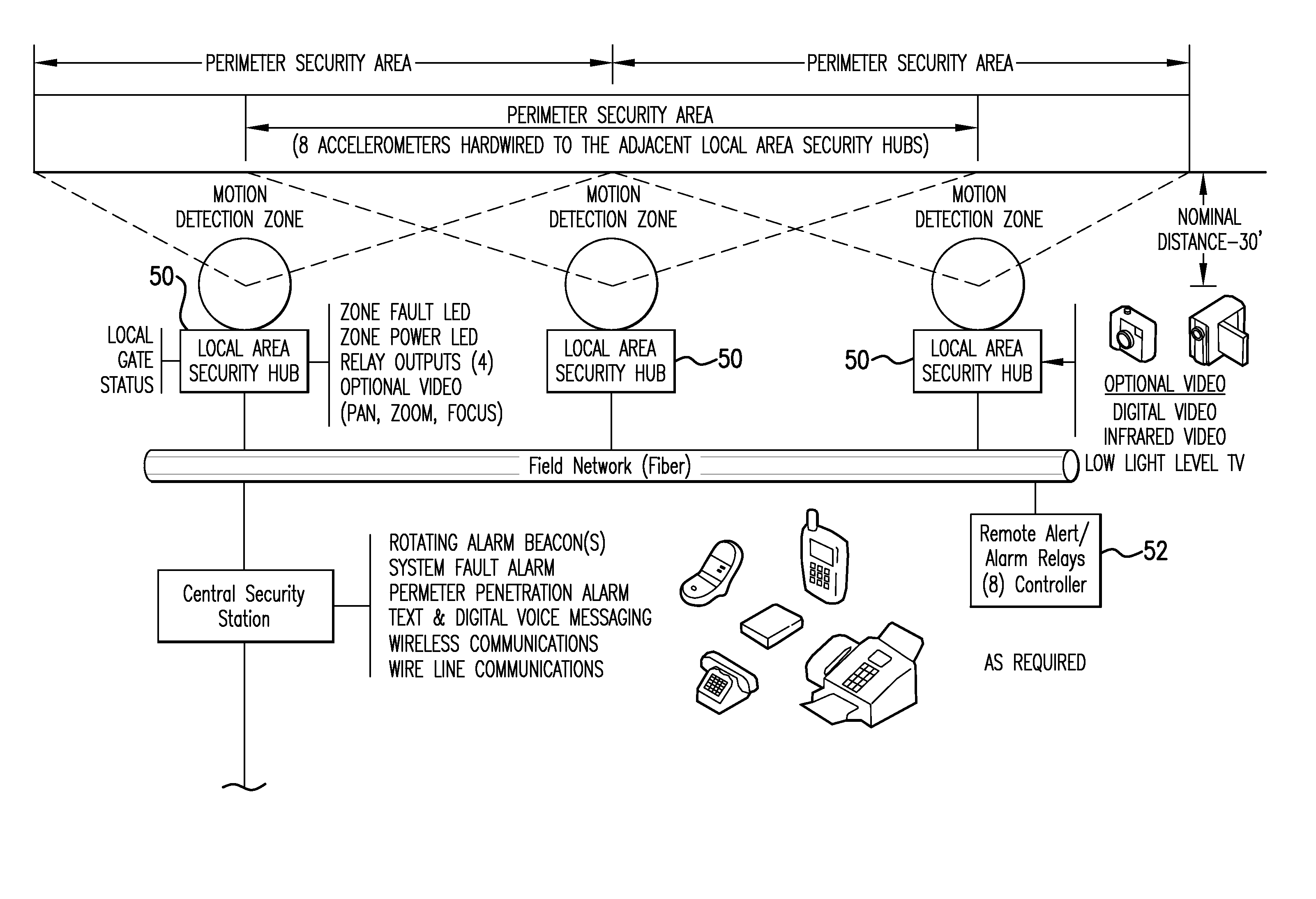
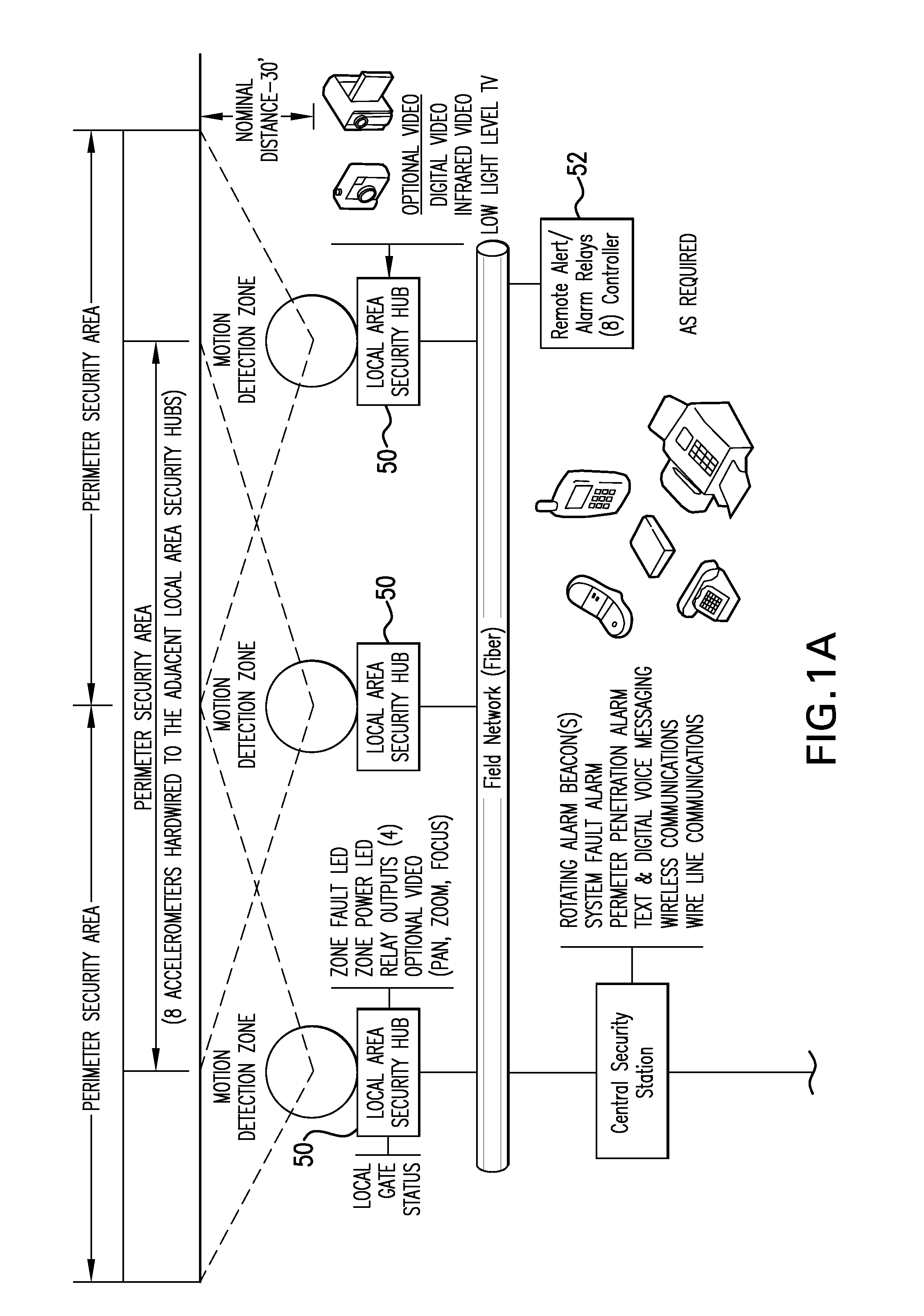
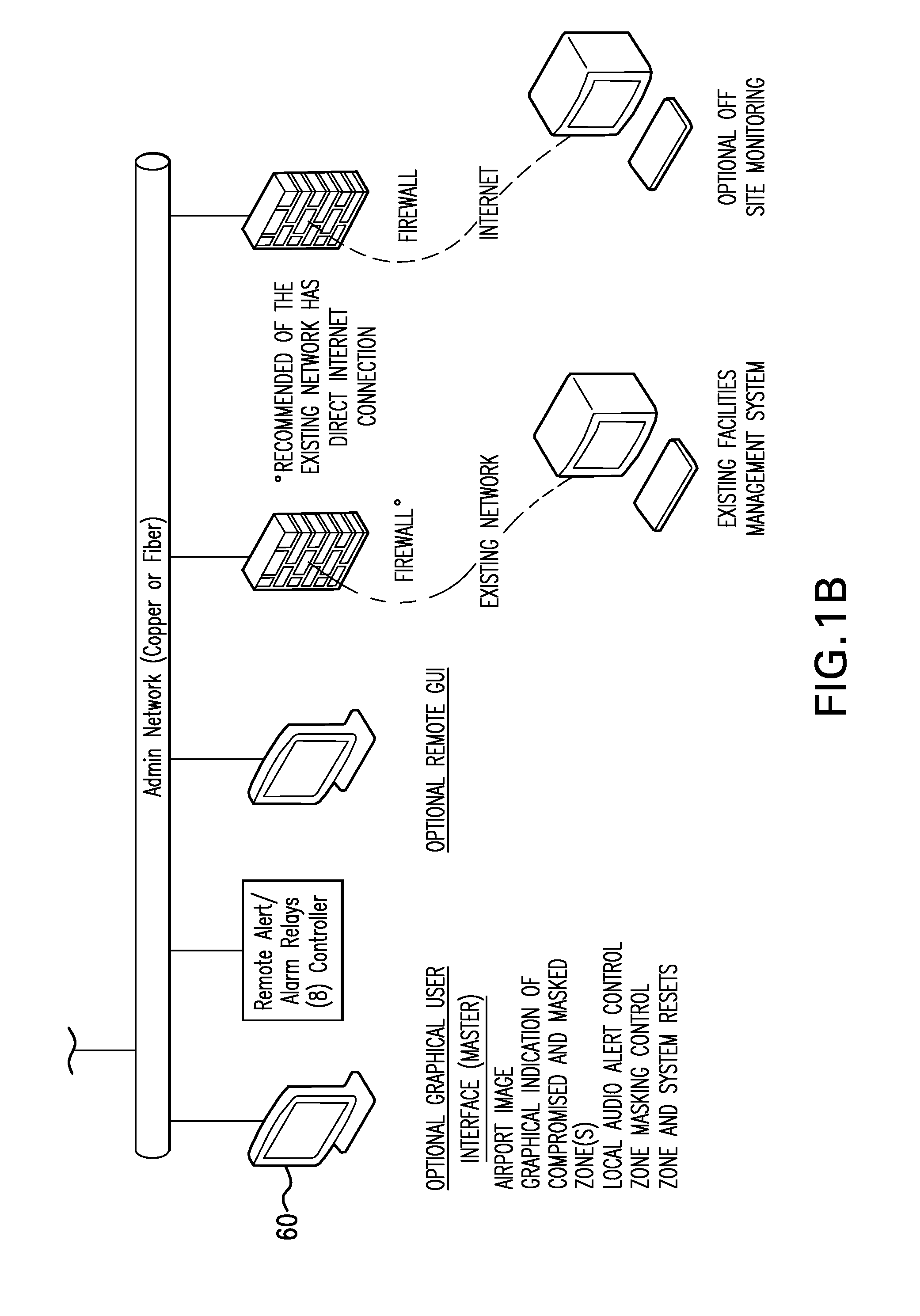
However, none of the conventional detection technologies provides a flexible and scalable system or method for collecting data from a variety of sensor components and communicating that information to an intelligent (i.e., rules-based) communications network, such as a central security processor, or that has the capability to drive a variety of lighting output devices as well as graphical interfaces, such as security monitors or mobile hand-held devices.
Further, none of the conventional perimeter detection technologies can easily incorporate the use of a combination of sensor technologies or can easily fuse data from motion or ground sensors or can easily, when placed within a perimeter boundary, reinforce fence-line detection and expand perimeter detection.
None of the conventional perimeter detection technologies acquires the data from multiple types of sensors, converts the data into a common format, and then processes the commonly formatted data according to predefined rules that drive outputs.

Method used


Image

  • Surveillance and warning system
  • Surveillance and warning system
  • Surveillance and warning system

Examples


Embodiment Construction

[0096]In a preferred embodiment of the system according to the present invention, as shown schematically in FIGS. 2, 3, and 4, an airfield runway occupancy warning system 10 provides critical runway status alerts to both flight crew approaching an airfield and air traffic controllers managing ground traffic. The primary components of such a runway occupancy warning system (ROWS™) include: a detection system consists of one or more detection hubs 100, airfield output devices 102 (including all FAROS, GAROS, and CTAF-RORS signals), an airfield communications network 104, and a runway operations processing electronics unit (“ROPE”) 106.

[0097]The runway occupancy warning system 10 can stand alone to operate without an air traffic control tower, or can be used in combination with an air traffic controller surveillance system 108, such as a GUI 110, to provide full tower and airfield detection capabilities.

[0098]As shown in FIG. 4, the runway occupancy warning system according to the pres...


PUM


Abstract

A system and method for providing entry-point, boundary-line, and presence intrusion detection by means of an intelligent controller process capable of driving both field alert / alarm systems and security station monitoring devices and for providing occupancy warnings and critical status alerts, one embodiment providing runway occupancy warnings and critical runway status alerts to both flight crew approaching an airfield and air traffic controllers managing ground traffic, the system including: a detection system, airfield output devices (including all FAROS, GAROS and CTAF Runway Occupancy Radio Signals (RORS)), an airfield communications network, a centralized data processing unit that contains all of the algorithms to drive light control, logging, and an optional administrative network layer that hosts a graphical user interface.

Description

STATEMENT REGARDING FEDERALLY SPONSORED RESEARCH OR DEVELOPMENT[0001]The U.S. Government has a paid-up license in this invention and the right in limited circumstances to require the patent owner to license others on reasonable terms as provided for by the terms of Prime Contract No. DTFA03-99-D-00017 / 0018, awarded by the Federal Aviation Administration (FAA) to The Titan Corporation, and as provided for by the terms of Subcontract No. 04-526 between The Titan Corporation and Patriot Technologies, LLC.CROSS-REFERENCE TO RELATED APPLICATIONS[0002]NoneREFERENCE TO SEQUENCE LISTING, A TABLE, OR A COMPUTER PROGRAM LISTING COMPACT DISK APPENDIX[0003]NoneBACKGROUND OF THE INVENTION[0004]1. Field of the Invention[0005]The present invention relates generally to a system and method for providing perimeter security and, more specifically to a system and method for providing entry-point, boundary-line, and presence intrusion detection by means of an intelligent controller process capable of dr...

Claims


Application Information

Patent Timeline
IPC IPC(8): G01S13/04G01S13/93
CPCG01S7/003G01S13/87G08G5/065G08G5/0026G08G5/0082G01S2013/916
Inventor HUTHOEFER, VIRGINIA LORRAINEHUTHOEFER, GERALD WALLACE
Owner PATRIOT TECH
Learn More