
Control device for mobile unit

Active Publication Date: 2009-08-06
TOYOTA JIDOSHA KK
View PDF5 Cites 8 Cited by
  • Summary
  • Abstract
  • Description
  • Claims
  • Application Information

AI Technical Summary

Benefits of technology

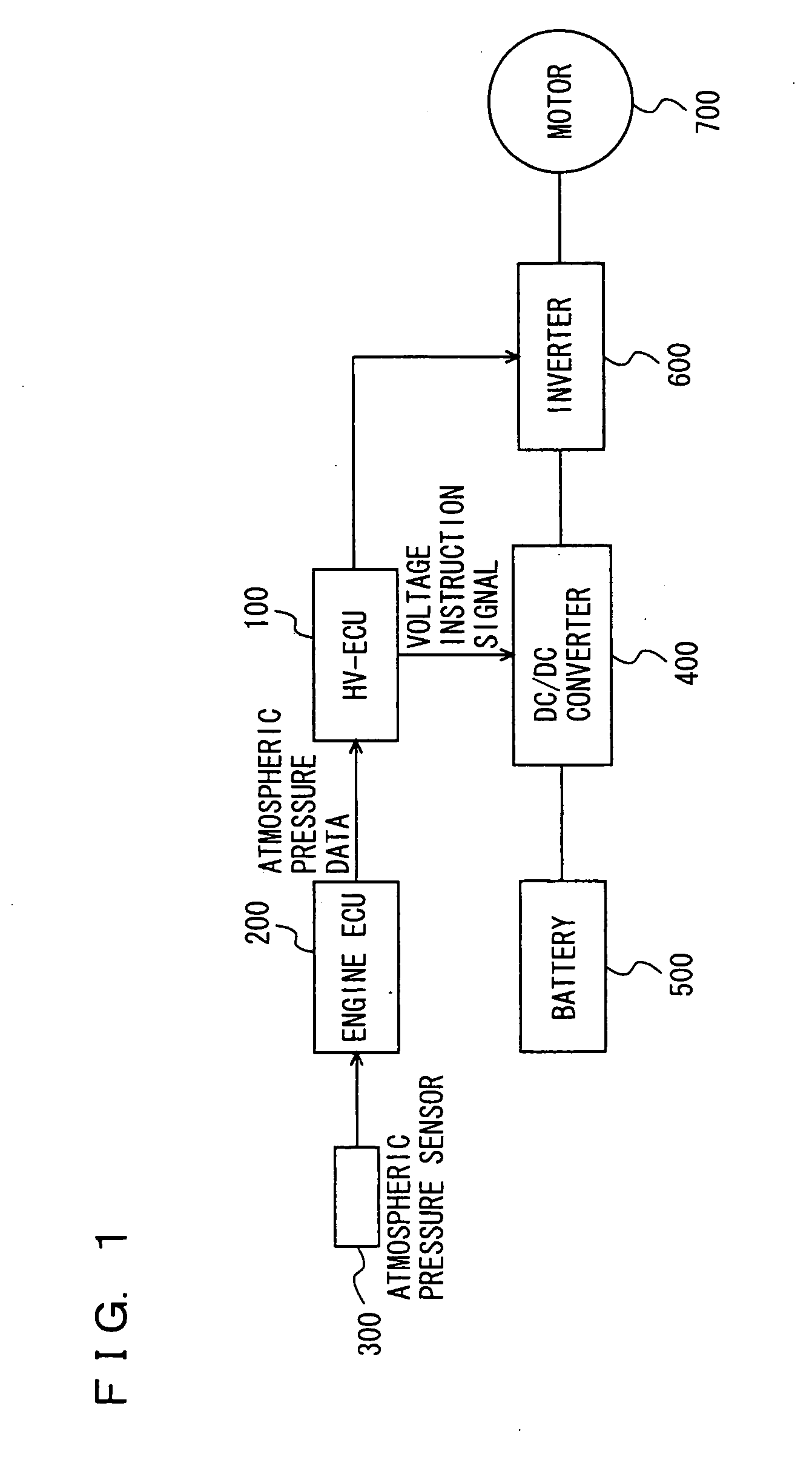
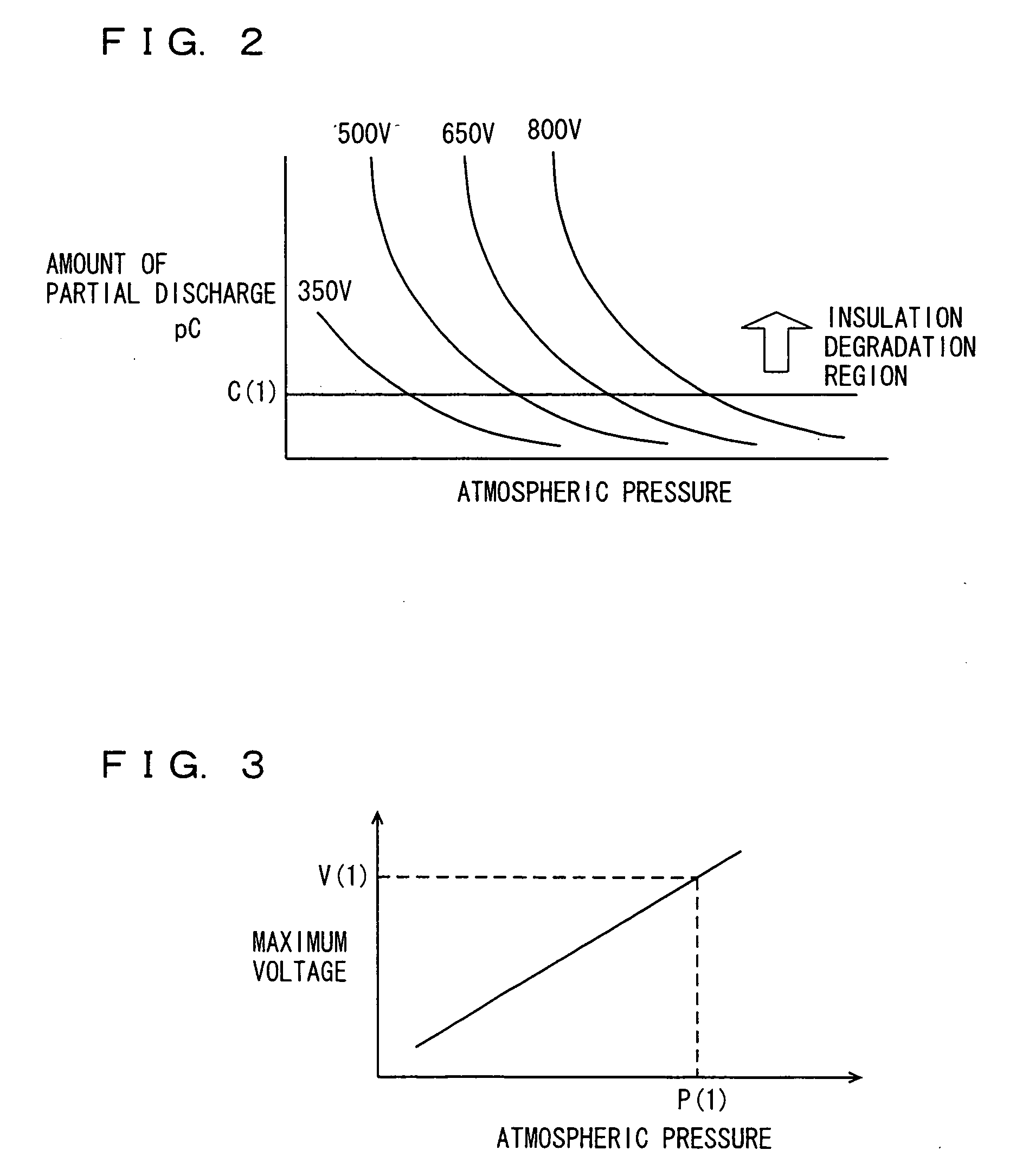
[0007]According to the present invention, the control unit sets a voltage value that is to be supplied to the motor and the electrical equipment, in accordance with the detected atmospheric pressure. The control unit controls the motor based on the set voltage value. For example, the control unit sets a voltage value that is to be supplied to the motor and the electrical equipment such that an amount of partial discharge falls within a permissible range where acceleration of degradation in the insulation performance of insulators can be suppressed at the detected atmospheric pressure. That is, the voltage value at which the amount of partial discharge falls within the permissible range is set under an environment where the atmospheric pressure is relatively low, such as in a highland, (for example, the voltage value lower than a voltage value at normal atmospheric pressure is set), so that an increase in amount of partial discharge can be suppressed. As a result, deterioration in the insulation performance of the insulators located within the motor and the electrical equipment can be suppressed. Therefore, there can be provided a control device for a mobile unit in which the insulation performance is ensured in accordance with a change in atmospheric pressure.
[0011]According to the present invention, the control value is a resistance value of a gate resistance provided between the switching element and the driving circuit. For example, if a resistance value larger than the resistance value of the gate resistance at normal atmospheric pressure is set under the environment where the atmospheric pressure is relatively low, such as in the highland, rising of a switching voltage is moderated. Consequently, a peak value of a surge voltage can be reduced. As a result, a reduction in the peak value of the surge voltage allows suppression of an increase in amount of partial discharge. Therefore, deterioration in the insulation performance of the insulators located within the motor and the electrical equipment can be suppressed.
[0013]According to the present invention, in the case where the load required at the motor is low, for example, the voltage value of a system voltage that is to be supplied to the motor and the electrical equipment is set to be low, so that deterioration in the efficiency of the inverter can be suppressed and the insulation performance can be ensured. On the other hand, in the case where the load required at the motor is high, the resistance value of the gate resistance in the inverter is set to be large, so that deterioration in the performance and efficiency of the motor can be suppressed and the insulation performance can be ensured. Therefore, any one of the voltage value and the resistance value is set, so that deterioration in the insulation performance can be suppressed and the motor can be controlled in accordance with the required load.

Problems solved by technology

Furthermore, the durability life is shortened.
Since a change in atmospheric pressure is not taken into consideration in the vehicle power control device disclosed in the above publication, the problems described above may arise.

Method used


Image

  • Control device for mobile unit
  • Control device for mobile unit
  • Control device for mobile unit

Examples


first embodiment

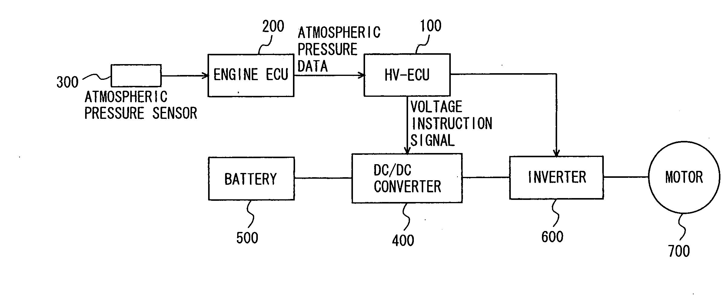
[0024]As shown in FIG. 1, a vehicle on which a control device for a mobile unit according to the present embodiment is mounted has an HV-ECU (Hybrid Vehicle-Electronic Control Unit) 100, an engine ECU 200, a DC / DC converter 400, a battery 500, an inverter 600, and a motor 700 mounted thereon. It should be noted that the vehicle control device according to the present embodiment is implemented by a program executed in HV-ECU 100.

[0025]Battery 500 is not limited in particular, as long as battery 500 is a chargeable secondary battery. Battery 500 may be, for example, a nickel hydride battery or a lithium ion battery.

[0026]DC / DC converter 400 boosts a DC voltage of battery 500. DC / DC converter 400 controls a boost voltage in response to a control signal received from HV-ECU 100.

[0027]Inverter 600 converts the DC voltage boosted at DC / DC converter 400 to an AC voltage. Inverter 600 controls the AC voltage to be supplied to motor 700, in response to a control signal received from HV-ECU 1...

second embodiment

[0040]A control device for a mobile unit according to a second embodiment will be described hereinafter. A vehicle having the control device for a mobile unit according to the present embodiment mounted thereon is different from the vehicle having the control device for a mobile unit according to the above-described first embodiment mounted thereon in terms of a configuration of inverter 600. The configuration of the vehicle having the control device for a mobile unit according to the present embodiment mounted thereon is otherwise the same as that of the vehicle having the control device for a mobile unit according to the above-described first embodiment mounted thereon. They are represented by the same reference characters. The functions are also the same. Therefore, the detailed description of those will not be repeated.

[0041]The present embodiment is characterized in that HV-ECU 100 sets a control value related to control of motor 700 in accordance with the atmospheric pressure ...


PUM


Abstract

An HV-ECU performs a step of detecting ans atmospheric pressure, a step of calculating a maximum value of a boost voltage corresponding to the atmospheric pressure by using a map, and a step of setting the maximum value as a system voltage value and controlling a DC / DC converter.Moreover, the HV-ECU may calculate a resistance value of a gate resistance of a switching element corresponding to the atmospheric pressure by using the map and control the gate resistance to achieve the set resistance value.

Description

TECHNICAL FIELD[0001]The present invention relates to a control device for a mobile unit, and in particular, to a control device controlling a motor and electrical equipment mounted on a mobile unit in accordance with an atmospheric pressure.BACKGROUND ART[0002]In recent years, a hybrid vehicle, a fuel cell vehicle, an electric vehicle and the like that run by using a driving force from a motor are attracting attention as one of the measures against environmental issues. On these vehicles, electrical equipment such as an inverter circuit supplying electric power to the motor is mounted. The electrical equipment drives the motor at high voltage, and it is necessary to ensure insulation. As a vehicle having such electrical equipment and motor mounted thereon, Japanese Patent Laying-Open No. 2004-208409, for example, discloses a vehicle on which a vehicle power control device capable of reducing a loss while responding excellently to various operating modes required by various rotating...

Claims


Application Information

Patent Timeline
IPC IPC(8): B60L9/00B60W10/04B60W20/00B60L50/10
CPCB60L3/003B60L15/20B60L2210/10B60W10/08B60W20/00B60W2550/12Y10T477/62429Y02T10/642Y02T10/7216Y02T10/7275Y10T477/624Y10T477/387H02P29/028H02P29/032B60L3/0061B60L3/0069B60W2555/20B60L50/60Y02T10/64Y02T10/70Y02T10/72B60W20/10B60W10/24B60W2555/00
Inventor MATSUMOTO, KATSUNARI
Owner TOYOTA JIDOSHA KK
Learn More