
Portable drilling device

a drilling device and portability technology, applied in the direction of portable drilling machines, programme control, instruments, etc., can solve problems such as motor burnou

Active Publication Date: 2009-08-06
NITTO KOHKI CO LTD
View PDF11 Cites 51 Cited by
  • Summary
  • Abstract
  • Description
  • Claims
  • Application Information

AI Technical Summary

Benefits of technology

[0010]In view of the foregoing, it is an object of the present invention to prevent recurrence of an overload condition by automatically restoring the motor if the overload condition is vanished after occurrence of the overload condition and by not restoring the motor if the overload condition continues for a predetermined period, thereby improving operability, safety, and workability.Means for Solving the Problems:
[0051]As described above, according to the processes in the second embodiment, the motor supply voltage is gradually reduced at step S310, whereby the force of the motor is reduced to prevent the cutting edge of the cutting tool from being damaged. Further, as is the case with the first embodiment, the motor supply voltage is maintained at the predetermined value at steps S312 and S313 in a state in which the load current value IL is larger than the reference value Vref4. Then, the motor is stopped or operated in the normal condition, according to the overload condition. Therefore, even if the process at step S307 for completely stopping the motor 12 is executed, damage on the cutting edge of the cutting tool can be prevented because the force has already been reduced. Further, as is the case with the first embodiment, it is possible to improve workability and to prevent the motor from burning out in the magnetic base drilling device.

Problems solved by technology

Therefore, in a case where a low-power motor is used, if an overload condition continues for a long period, the motor may burn out due to an overcurrent generated in the overload condition.

Method used


Image

  • Portable drilling device
  • Portable drilling device
  • Portable drilling device

Examples


Embodiment Construction

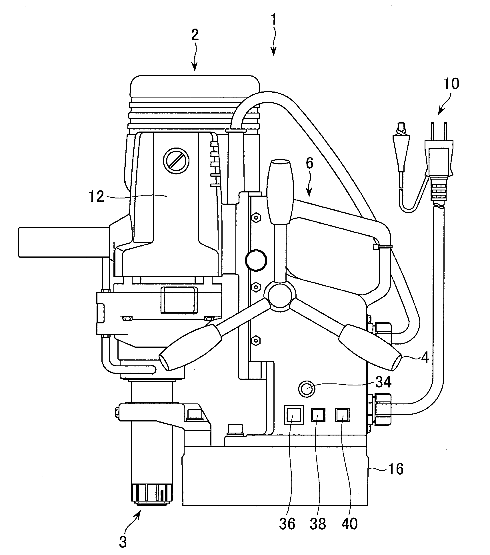
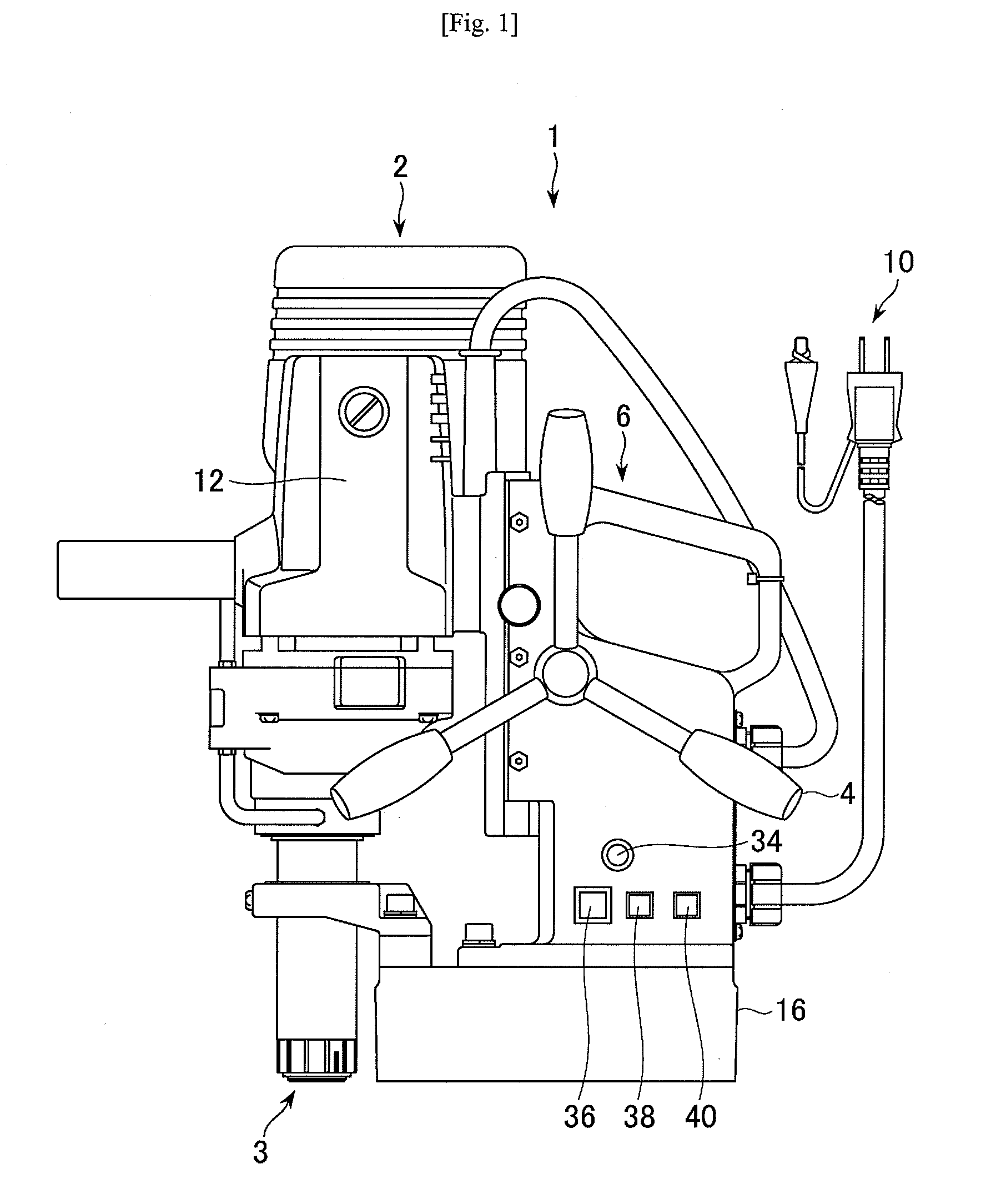
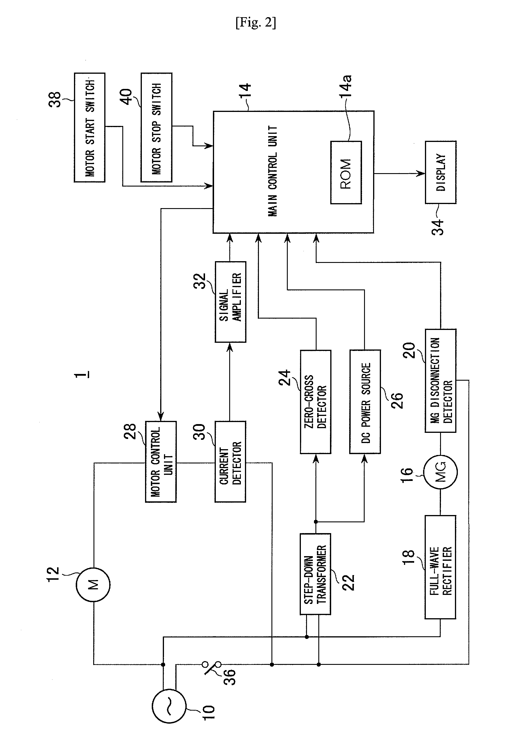
[0021]A magnetic base drilling device according to an embodiment of a portable drilling device of the present invention will now be described with reference to FIGS. 1 to 4. FIG. 1 is an external view of a magnetic base drilling device according to the present invention. FIG. 2 is a block diagram showing a control structure of the magnetic base drilling device. The magnetic base drilling device 1 is mainly composed of a body 2, and a supporting part 6 for supporting a cutting tool held by a chuck 3 such that the cutting tool can be moved toward and away from a workpiece by rotating a operating handle 4. The magnetic base drilling device 1 includes a motor 12 powered by, for example, a 100 V AC power source 10, a main control unit 14 for motor control and display control of the motor control status, a magnet (MG) 16 for, when energized, generating a predetermined magnetic force, a full-wave rectifier 18 for supplying to the magnet 16 a DC output obtained by full-wave rectifying of th...


PUM

PropertyMeasurementUnit
frequencyaaaaaaaaaa
frequencyaaaaaaaaaa
supply voltageaaaaaaaaaa

Abstract

It is an object of the present invention to prevent recurrence of an overload condition after occurrence of the overload condition, thereby improving operability and safety in a drilling device. A motor 12 for rotating a drill is connected to an AC power source 10 through a motor control unit 28, a current detector 30, and a power switch 36. A magnet 16 is also connected to the AC power source 10 through the power switch 36 and a full-wave rectifier 18. The motor control unit 28 rotationally drives the motor on the basis of a signal sent from a main control unit according to a state in which a motor start switch 38 is on. The main control unit 14 controls the motor control unit 28 to gradually reduce a supply voltage to the motor 12 when the motor 12 becomes overloaded, to gradually increase the voltage to the normal power supply condition when the overload condition is vanished, and to stop power supply to the motor 12 if the overload condition continues for a predetermined period.

Description

TECHNICAL FIELD[0001]The present invention relates to a portable drilling device having a structure in which a body thereof can be secured to a workpiece by means of an electromagnet or the like, and a cutting tool, such as a drill, attached to an output shaft of a motor is manually moved toward and away from the workpiece.BACKGROUND ART[0002]As machine tools for drilling holes in a workpiece, there exist portable drilling devices having portability and a structure in which a body thereof can be secured to a workpiece by means of an attracting force of an electromagnet, a vise, or the like. Generally, drilling devices have a structure in which a drill is connected directly to a drive motor (hereinafter, referred to as “a motor” for short). A load acting on the drill significantly fluctuates according to a contact condition of the drill with the workpiece, a downward force applied to the drill, material properties of the workpiece, and so on. This fluctuation is transmitted directly ...

Claims


Application Information

Patent Timeline
Patent Type & Authority Applications(United States)
IPC IPC(8): B23B39/24
CPCB23B45/02B23B2260/062B23B2260/122B23B2270/32B25H1/0071G05B19/4062Y10T408/14G05B2219/37342G05B2219/42286G05B2219/42289G05B2219/45127Y10S388/937G05B2219/37285
Inventor OTSUKA, KENJIASANO, OSAMU
Owner NITTO KOHKI CO LTD
Learn More