Overheat protection circuit
a protection circuit and overheat protection technology, applied in the direction of heat measurement, screws, instruments, etc., can solve the problems and achieve the effect of reducing the cost of overheat protection and the scale of the circui
- Summary
- Abstract
- Description
- Claims
- Application Information
AI Technical Summary
Benefits of technology
Problems solved by technology
Method used
Image

Examples
first embodiment
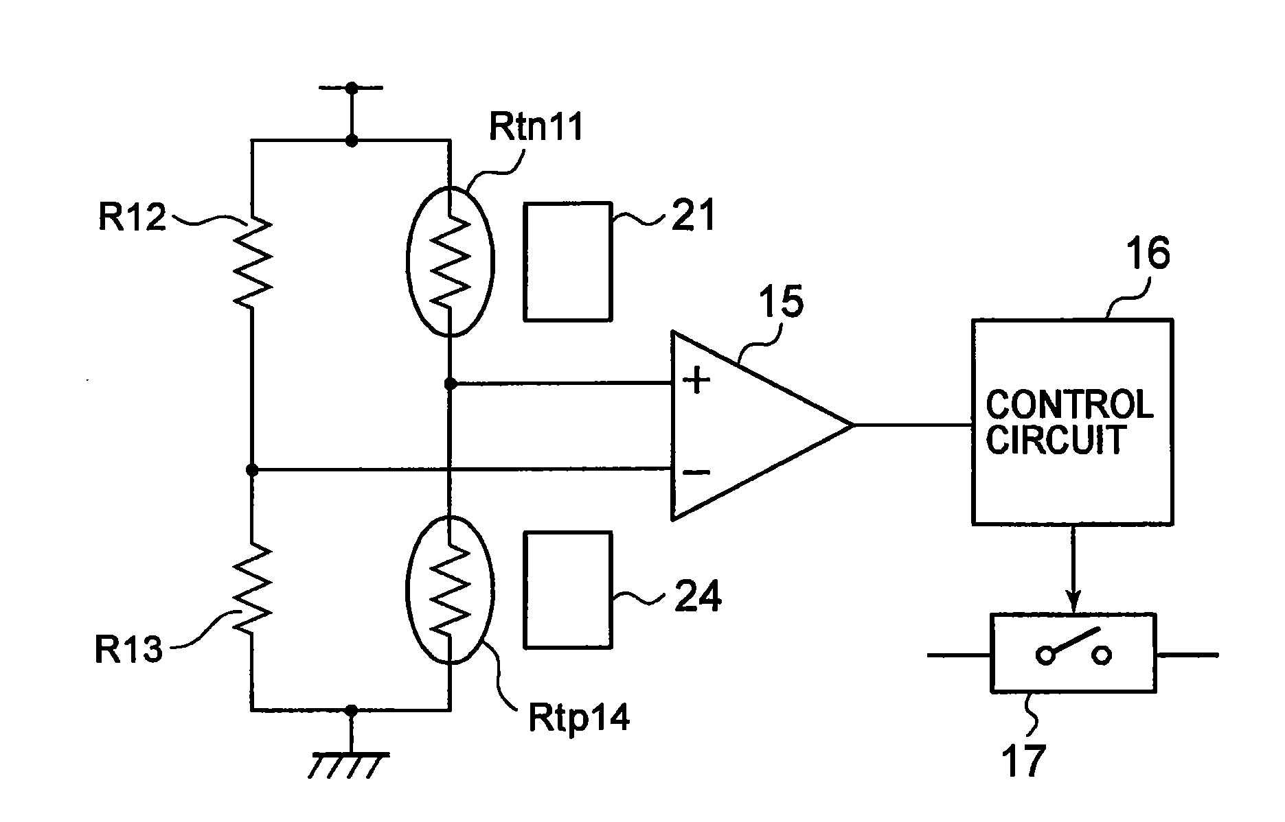
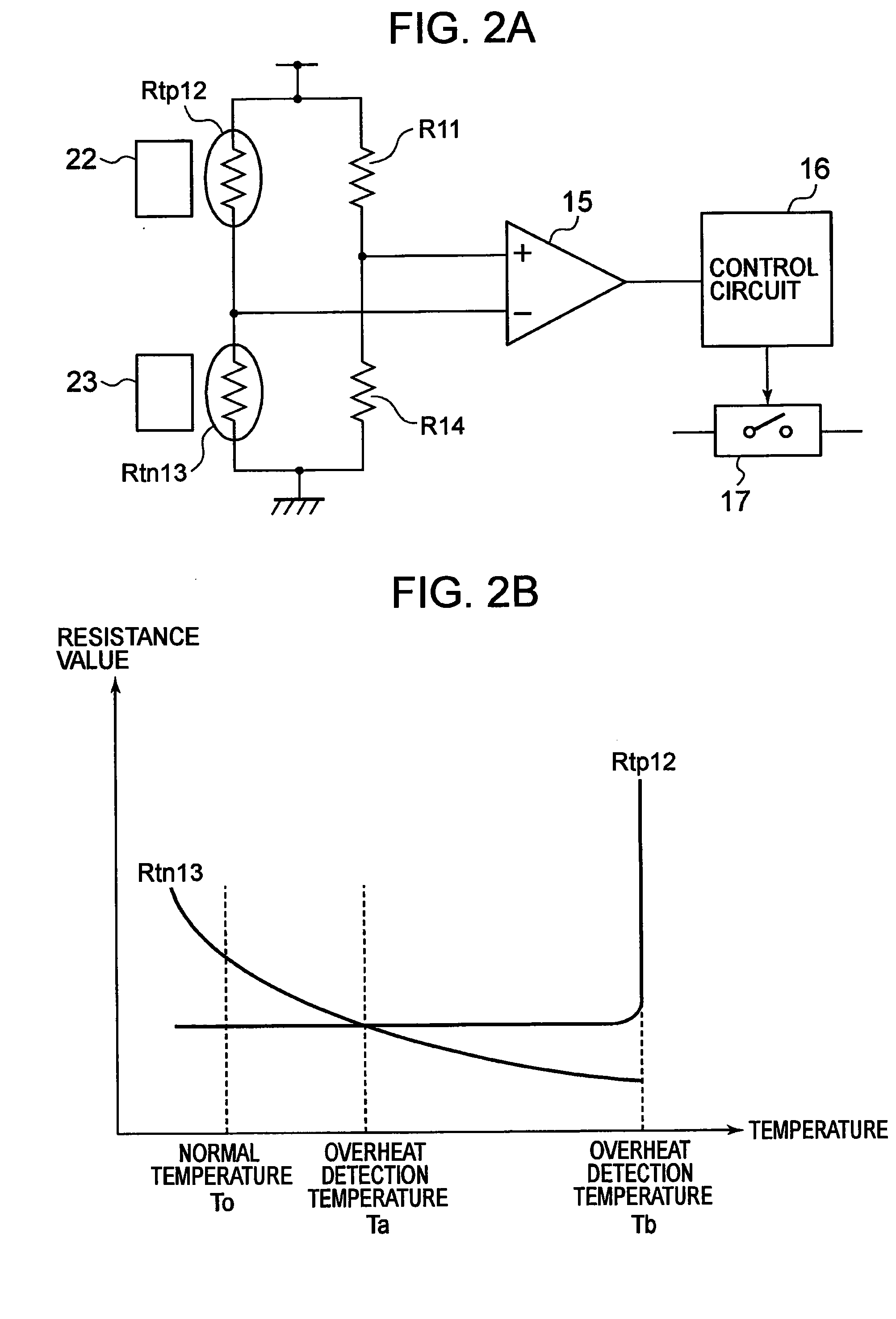
[0037]A structure of an overheat protection circuit according to a first embodiment of the present invention is described. FIG. 1A is a diagram illustrating the overheat protection circuit according to the first embodiment of the present invention. FIG. 1B is a graph illustrating a relation between resistance value and temperature of the overheat protection circuit according to the first embodiment of the present invention.
[0038]As illustrated in FIG. 1A, the overheat protection circuit includes a resistor Rtn11, a resistor R12, a resistor R13, a resistor Rtp14, a comparator circuit 15, a control circuit 16, and a switch circuit 17. A part 21 is provided in the vicinity of the resistor Rtn11. A part 24 is provided in the vicinity of the resistor Rtp14.
[0039]One end of the resistor Rtn11 is provided at a power source terminal and the other end thereof is provided at a non-inverting input terminal of the comparator circuit 15. One end of the resistor R12 is provided at the power sourc...
second embodiment
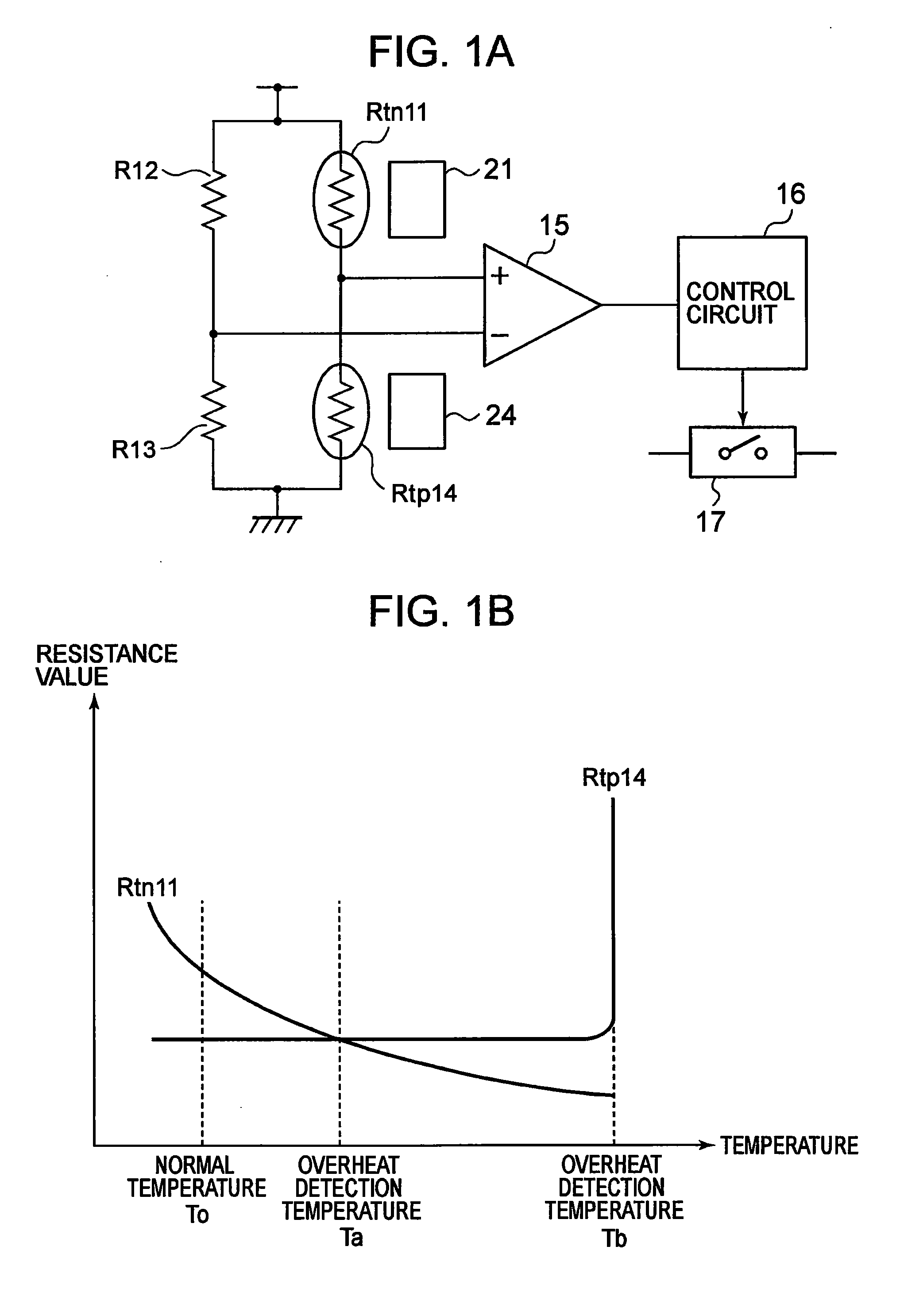
[0051]A structure of an overheat protection circuit according to a second embodiment of the present invention is described. FIG. 2A is a diagram illustrating the overheat protection circuit according to the second embodiment of the present invention. FIG. 2B is a graph illustrating a relation between resistance value and temperature of the overheat protection circuit according to the second embodiment of the present invention.
[0052]As illustrated in FIG. 2A, the overheat protection circuit according to the second embodiment of the present invention is different from the overheat protection circuit according to the first embodiment of the present invention in that the resistor Rtn11 is changed to a resistor R11, the resistor R12 is changed to a resistor Rtp12, the resistor R13 is changed to a resistor Rtn13, and the resistor Rtp14 is changed to a resistor R14. In addition, the part 21 is removed, a part 22 is provided in the vicinity of the resistor Rtp12, a part 23 is provided in th...
third embodiment
[0057]Next, a structure of an overheat protection circuit according to a third embodiment of the present invention is described. FIG. 3A is a diagram illustrating the overheat protection circuit according to the third embodiment of the present invention. FIG. 3B is a graph illustrating a relation between resistance value and temperature of the overheat protection circuit according to the third embodiment of the present invention.
[0058]As illustrated in FIG. 3A, the overheat protection circuit according to the third embodiment of the present invention is different from the overheat protection circuit according to the first embodiment of the present invention in that the resistor R12 is changed to the resistor Rtp12, and the resistor Rtp14 is changed to the resistor R14. In addition, the part 22 is provided in the vicinity of the resistor Rtp12, and the part 24 is removed.
[0059]The resistor Rtn11 has a negative temperature coefficient. The resistor Rtp12 has a positive temperature coe...
PUM
 Abstract
Description
Claims
Application Information
 - R&D
- Intellectual Property
- Life Sciences
- Materials
- Tech Scout
- Unparalleled Data Quality
- Higher Quality Content
- 60% Fewer Hallucinations
Browse by: Latest US Patents, China's latest patents, Technical Efficacy Thesaurus, Application Domain, Technology Topic, Popular Technical Reports.
© 2025 PatSnap. All rights reserved.Legal|Privacy policy|Modern Slavery Act Transparency Statement|Sitemap|About US| Contact US: help@patsnap.com