
Blood treatment filter and blood treatment circuit

a technology of filter and blood, which is applied in the direction of filtration separation, machine/engine, separation process, etc., can solve the problems of reducing the platelet recovery rate in the obtained blood component product (final blood product), difficult to keep sufficiently high levels of both leukocyte removal rate and platelet recovery rate, and virtually impossible to prepare a platelet product, etc., to achieve excellent operational efficiency and reduce the time for filtering blood

Inactive Publication Date: 2009-07-09
TERUMO KK
View PDF7 Cites 35 Cited by
  • Summary
  • Abstract
  • Description
  • Claims
  • Application Information

AI Technical Summary

Benefits of technology

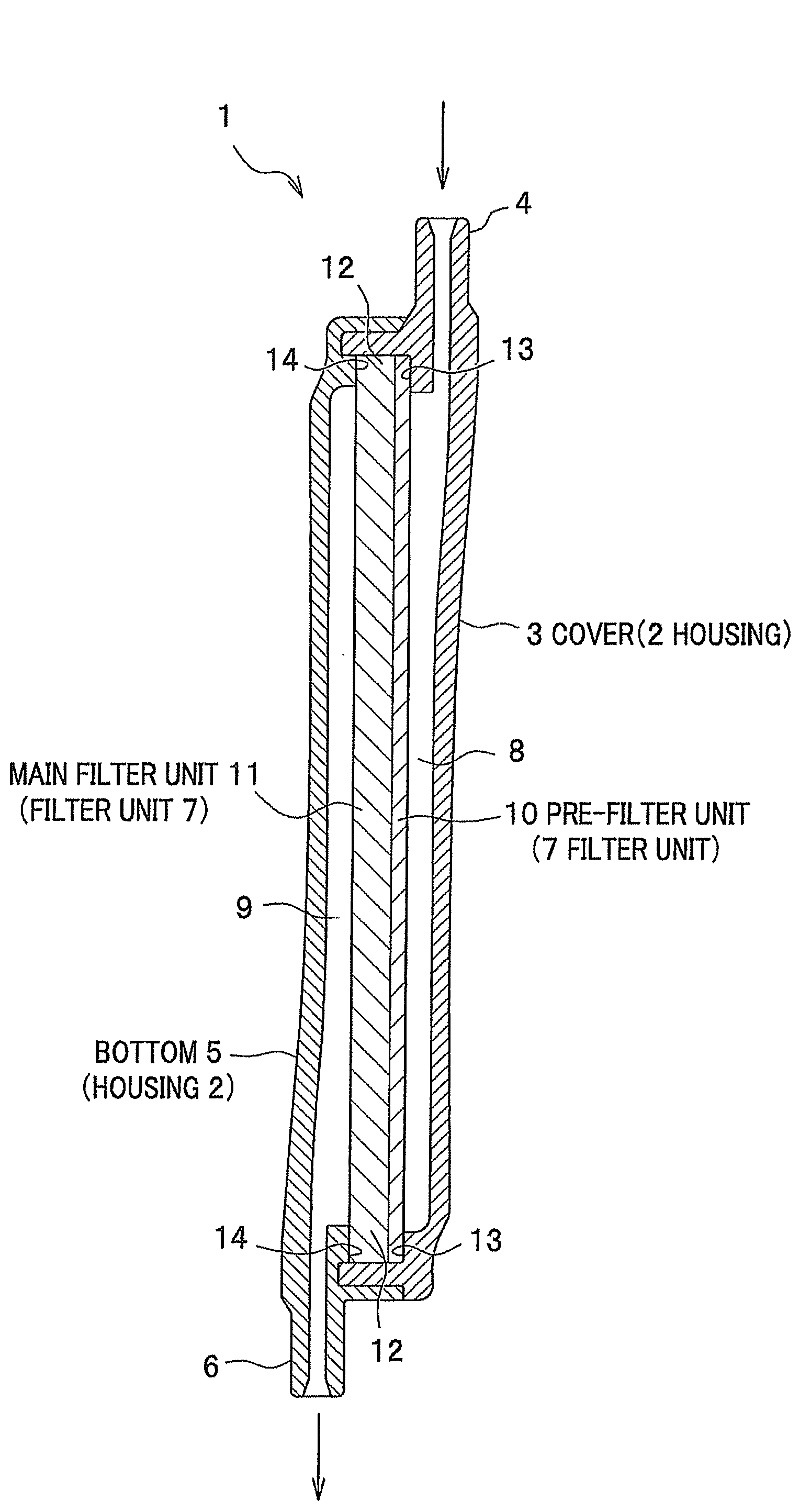
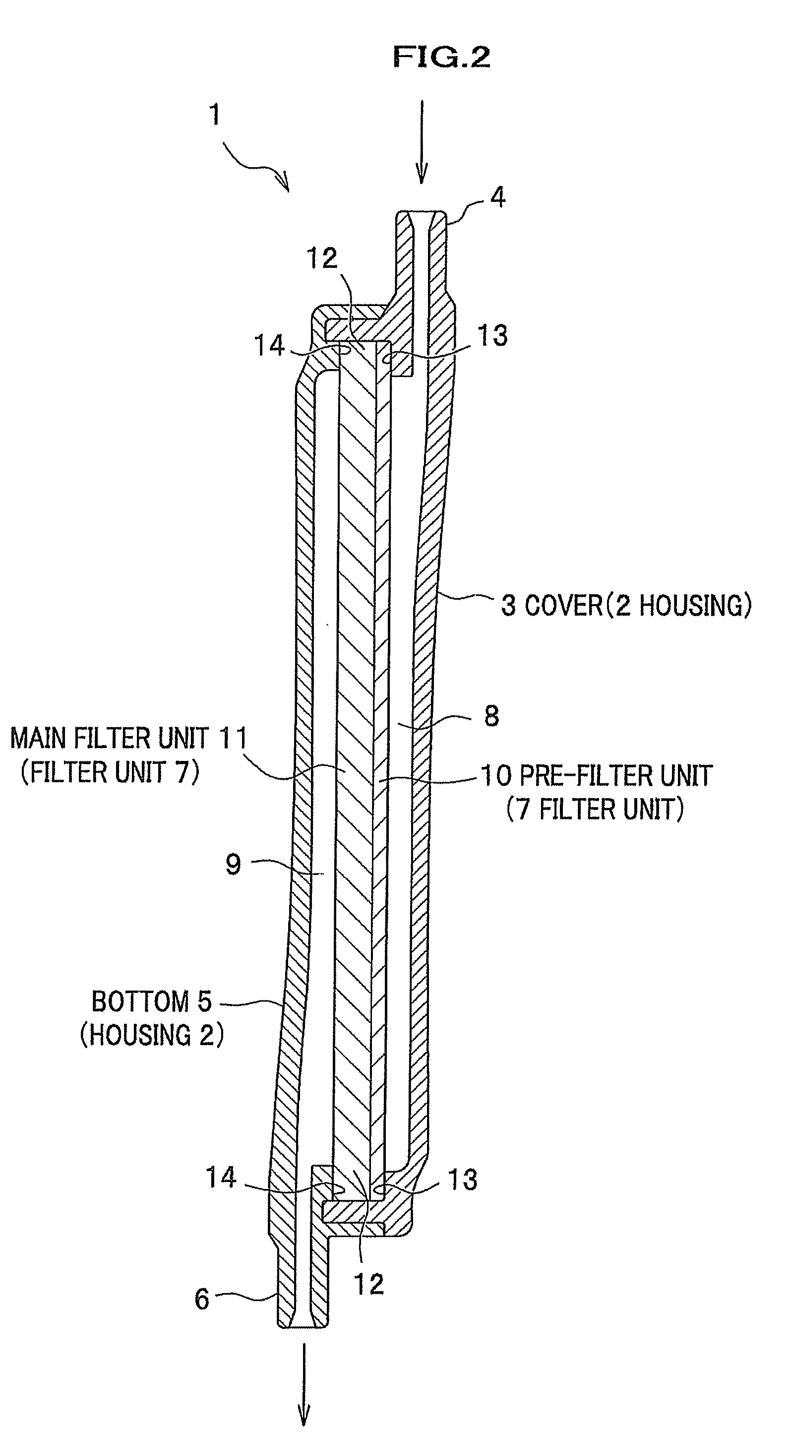
[0012]According to the above-mentioned construction, movement of blood cells flowing into the main filter unit is adjusted and stagnation of the influx blood cells is prevented, by providing the pre-filter unit at the up-stream side of the main filter unit capturing predetermined blood components; the pre-filter having a predetermined permeability rate of micro particles within a predetermined range of a particle size (6 μm) and not removing the blood components. Hereby, removing of the predetermined blood cell components and passage (recovery) of the remaining blood cell components besides the predetermined blood cell components are going smoothly in the main filter unit.
[0037]Further, according to the blood treatment filter and the blood treatment circuit, by defining the absolute surface zeta potential value, the removal rate of micro particles, the treated blood amount, or the volume rate of the filter unit to be within a predetermined range, it is possible to sufficiently satisfy the standard of the final blood product. For example, it is possible to satisfy that a leukocyte removal rate is more than 3.8 (−Log), a platelet recovery rate is more than 75%, and an erythrocyte recovery rate is more than 90%. Moreover, since it is possible to decrease time for filtering blood (filtration duration time) to be under 45 min, excellent operational efficiency for producing a blood product is achieved.

Problems solved by technology

It has been virtually impossible to prepare a platelet product by using a commercially available filter for a whole blood product because not only leukocytes but also platelets having high adhesion property are simultaneously removed from the whole blood product.
However, with respect to the leukocyte removal method disclosed in Japanese Patent Laid-Open Publication No. 2001-198213, there is a problem that it is difficult to keep sufficiently high levels of both leukocyte removal rate and platelet recovery rate for the obtained blood component product (final blood product) in an actual amount of treated blood assumed (max.
As a result, there is a problem that the platelet recovery rate in the obtained blood component product (final blood product) becomes to decrease.

Method used


Image

  • Blood treatment filter and blood treatment circuit
  • Blood treatment filter and blood treatment circuit
  • Blood treatment filter and blood treatment circuit

Examples


examples

[0093]The following is the detailed description about the embodiments which cover the blood treatment filter of the present invention.

examples 1 to 17

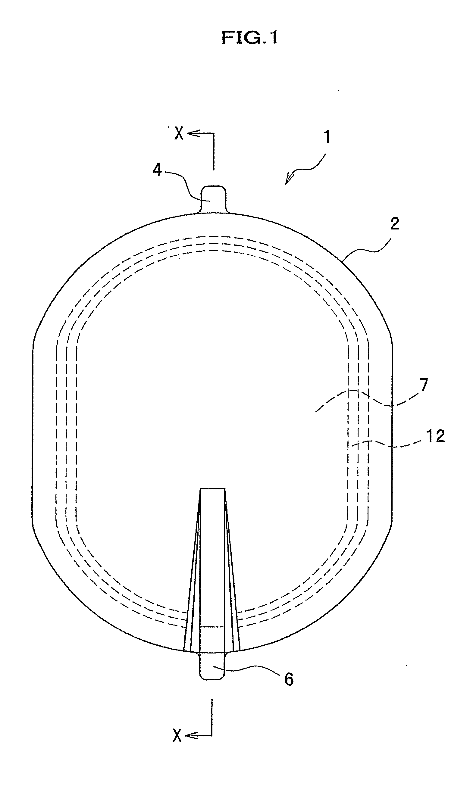
[0094]A blood treatment filter including a housing and a filter unit is assembled through the following steps. With respect to components, the housing includes a cover and a bottom which are made of polycarbonate with the shape shown in FIGS. 1 and 2. The filter unit includes a main filter unit made of a sponge-like porous membrane of polyether type polyurethane, and a pre-filter unit made of a sponge-like porous membrane of polyether type polyurethane. Firstly, the periphery of the filter unit assembled with the main filter and the pre-filter units is fusion-bonded by high frequency fusion-bonding, and the filter unit is held in the housing. Then, the periphery of the housing is fusion-bonded by high frequency fusion-bonding from the outside to prepare the blood treatment filter. Here, the effective area of the filter unit excluding the fusion-bonding part (non-filtering functional position) is 50 cm3.

example 18

[0095]A filter unit including a main filter unit and a pre-filter unit is held in a housing which includes a cover and a bottom. Both cover and the bottom are made of polycarbonate with the shape shown in FIGS. 1 and 2. The main filter unit is made of nonwoven fabric of polyethylene terephthalate having an average fiber diameter of 1.2 μm, and the pre-filter unit is made of a sponge-like porous membrane of polyether type polyurethane. The filter unit is fusion-bonded at the respective peripheries by high frequency fusion-bonding and is held in the housing. Then, the periphery of the housing including the filter unit is fusion-bonded by high frequency fusion-bonding to assemble the blood treatment filter. Herein, the effective area excluding the fusion-bonding part (non-filtering functional position) of the filter unit is 50 cm3.

[0096]Here, the surface of the main filter unit is covered with copolymer made of 2-hydroxyethyl methacrylate (HEMA), dimethylaminoethyl methacrylate (DM).


PUM

PropertyMeasurementUnit
Lengthaaaaaaaaaa
Fractionaaaaaaaaaa
Fractionaaaaaaaaaa

Abstract

A blood treatment filter which comprises a housing including an inlet and an outlet, and a filter unit for filtering blood containing erythrocytes, platelets and leukocytes as blood cell components is provided.The filter unit comprises a main filter unit which virtually removes predetermined cell components from blood and passes the remaining blood cell components, and a pre-filter unit which is arranged at the up-stream side of the main filter and virtually does not remove blood cell components.The pre-filter unit has a permeability rate of 70 to 90% for micro particles having an average particle size of 6 μm which are contained in a suspension and passed by gravity.

Description

BACKGROUND OF THE INVENTION[0001]1. Field of the Invention[0002]The present invention relates to a blood treatment filter and a blood treatment circuit for preparing a blood component product for blood transfusion.[0003]2. Description of Related Art[0004]Recently, blood transfusion of blood component products free of leukocytes has been widely used to prevent adverse effects which are caused by leukocytes. Here, removal methods for leukocytes are classified into two groups. One method is to remove leukocytes by filtering respective blood components prepared via centrifugal separation of blood (whole blood product) collected from a donor, through an appropriate filter for the respective blood component. The other method is to remove leukocytes by which a blood component product is prepared by removing leukocytes by filtering a whole blood product and separating the resulting blood product centrifugally.[0005]It has been virtually impossible to prepare a platelet product by using a co...

Claims


Application Information

Patent Timeline
IPC IPC(8): B01D35/30B01D35/06B01D35/02
CPCA61M1/0209A61M1/0222A61M1/3633A61M1/0231A61M1/0236
Inventor IMAI, TADASHIOHKAWARA, JUNICHIMURAKOSHI, MASAHIDE
Owner TERUMO KK
Learn More