
Solid electrolyte multilayer membrane, method and apparatus of producing the same, membrane electrode assembly, and fuel cell

a solid electrolyte and multi-layer membrane technology, applied in the direction of electrochemical generators, cell components, membranes, etc., can solve the problems of large and complicated production apparatus, high cost of solid electrolyte membrane and catalyst members, and risk of continuous production, etc., to promote redox reaction, low cost, and uniform quality

Inactive Publication Date: 2009-07-02
FUJIFILM CORP
View PDF5 Cites 7 Cited by
  • Summary
  • Abstract
  • Description
  • Claims
  • Application Information

AI Technical Summary

Benefits of technology

[0018]According to the present invention, it is possible to continuously produce the solid electrolyte multilayer membrane provided with the catalyst layers that promote the redox reaction at a low cost. The produced solid electrolyte multilayer membrane has uniform quality and excellent ionic conductivity. When the membrane electrode assembly using this solid electrolyte multilayer membrane is used for the fuel cell, the fuel cell realizes an excellent electromotive force.

Problems solved by technology

However, this method has problems in that the polymer may denature by heating, impurities in the polymer remain in the produced membrane, and the like.
On the other hand, the solution casting method has a problem in that its producing apparatuses become large and complicated since the method requires a producing apparatus of a solution, a solvent recovery device and the like.
The solid electrolyte membrane and the catalyst members are relatively expensive, hence continuously producing them carries a risk unless stable producing conditions are established.
Accordingly, it cannot be helped to make each member separately and combine them later, even though this method is inefficient.
However, in the above-noted Publication No. 9-320617, the solution casting method is denied, and there remains a problem in that the impurities contained in raw materials remain in the produced membrane.
The method disclosed in the above-noted Publication No. 2001-307752 has a problem in that it is difficult to disperse a complex consisted of the polymer and the inorganic compound.
The method disclosed in the above-noted Publication No. 2002-231270 has a problem in that its membrane producing step is complicated.
The method disclosed in the above-noted Publication No. 2004-079378 has a problem in that the produced membrane is not uniform in planarity and smoothness since it has micropores formed during the immersing in the aqueous solution.
However, it cannot be said that the methods are capable of continuously producing fuel cells integrally to have uniform quality without loss of the expensive catalyst and solid electrolyte.
In addition, both publications do not disclose or suggest improvement of fuel cell properties.
Without such methods, it is difficult to realize mass production of the fuel cell having high performance, at low cost.

Method used


Image

  • Solid electrolyte multilayer membrane, method and apparatus of producing the same, membrane electrode assembly, and fuel cell
  • Solid electrolyte multilayer membrane, method and apparatus of producing the same, membrane electrode assembly, and fuel cell
  • Solid electrolyte multilayer membrane, method and apparatus of producing the same, membrane electrode assembly, and fuel cell

Examples


example 1

[0139]Hereinafter, examples of the present invention are explained. In the following description, Experiment 1 of Example 1 and Experiment 1 of Example 2 are explained in detail. With respect to Experiments 2 to 7 of Example 1 and Experiments 2 to 6 of Example 2, conditions different from each Experiment 1 of Examples 1 and 2 are only explained. Note that Experiments 2 to 6 of Example 1 and Experiments 2 to 5 of Example 2 are the examples of the embodiments of the present invention. Experiments 1 and 7 of Example 1, and Experiments 1 and 6 of Example 2 are the comparative experiments of the embodiments of the present invention.

experiment 1

[0140]{Production of First, Second and Third dopes 114, 115 and 116}

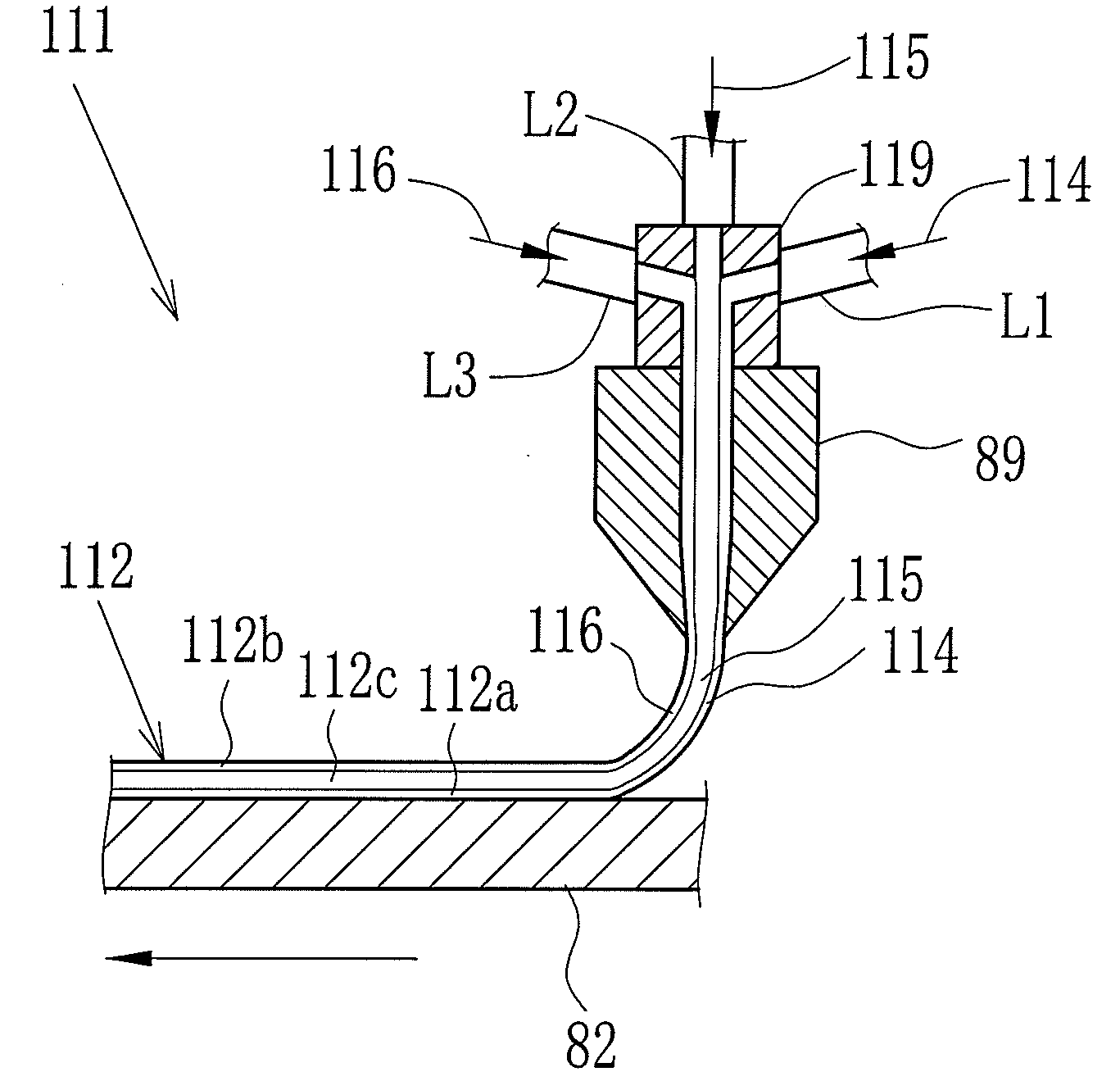
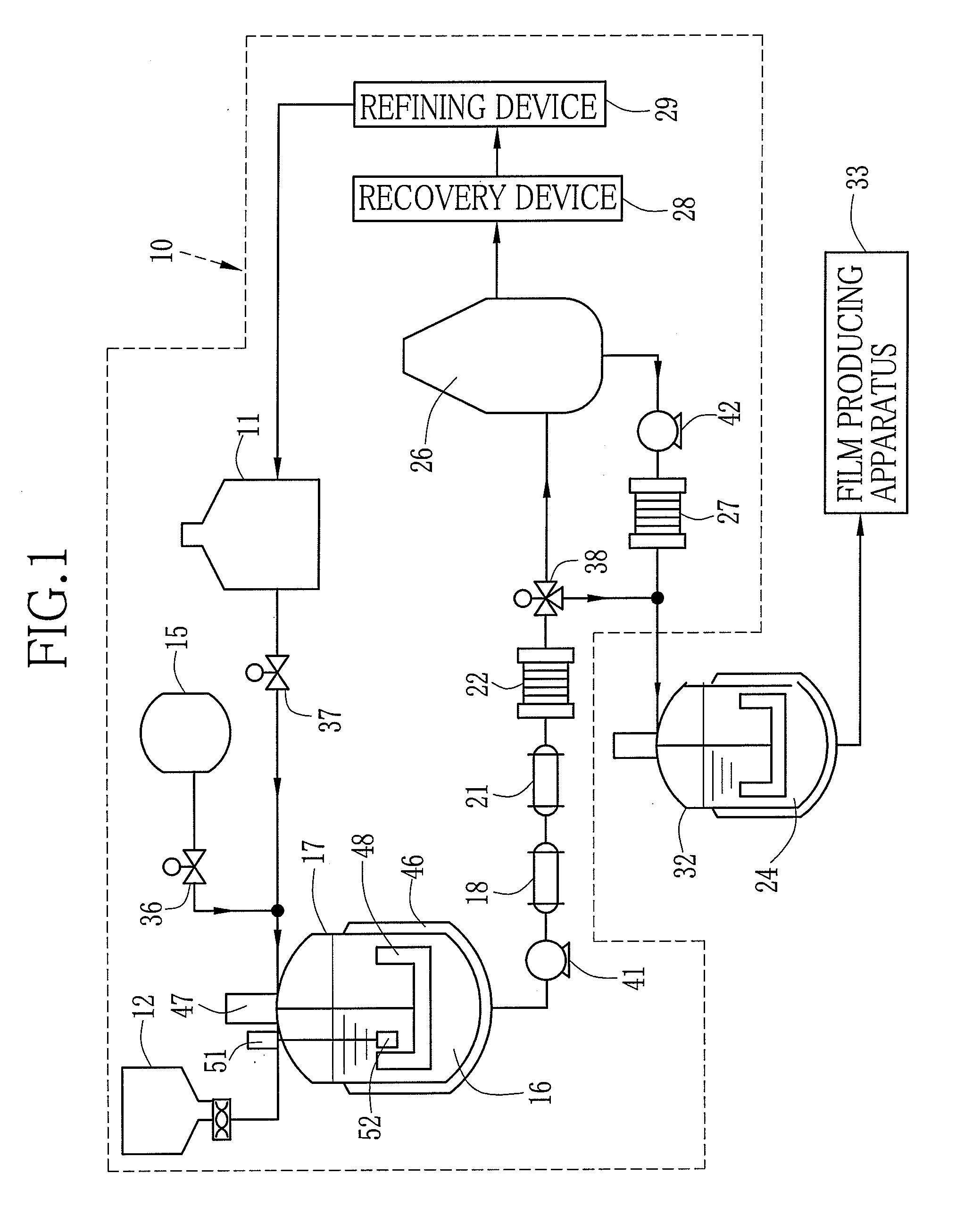
[0141]A material A was condensed by the flash device 26 and dried. Solid contents containing the dried material A was dissolved in the solvent according to the following composition, and the dopes having the solid contents of 30 wt. % were produced. The solvent was perfluorohexane. Note that catalyst fine particles did not dissolve in, but dispersed in the solvent. Additive rate of dichloromethane to the dope was varied in each Experiment 1 to 7 as shown in Table 1. The dichloromethane was the poor solvent of the dried material A. The dichloromethane was added to the first dope 114 and the third dope 116, but was not added to the second dope 115. Each Experiment 1 to 7 was performed with varying the additive rate of dichloromethane that was the poor solvent of the dried material A. The first to third dopes 114 to 116 in Experiments 1 to 7 all had 30 wt. % of the solid contents concentration. Note that the material A...

example 2

[0160]Solid contents containing a dried material B was dissolved in the solvent according to the following composition, and the first, second and third dopes 114, 115 and 116 having the solid contents of 30 wt. % were produced. The solvent was N-methylpyrrolidone. Note that catalyst fine particles did not dissolve in, but dispersed in the solvent. Note that the material B was sulfonated polyacrylonitrile styrene.

First dope 114:Dried material B10 pts. wtPt catalyst fine particles TEC10E50E20 pts. wt(manufactured by Tanaka Kikinzoku Kogyo K.K.)Second dope 115:Dried material BThird dope 116:Dried material B10 pts. wtPt—Ru catalyst fine particles TEC61E5420 pts. wt(manufactured by Tanaka Kikinzoku Kogyo K.K.)

{Production of Solid Electrolyte Multilayer Membrane 62}

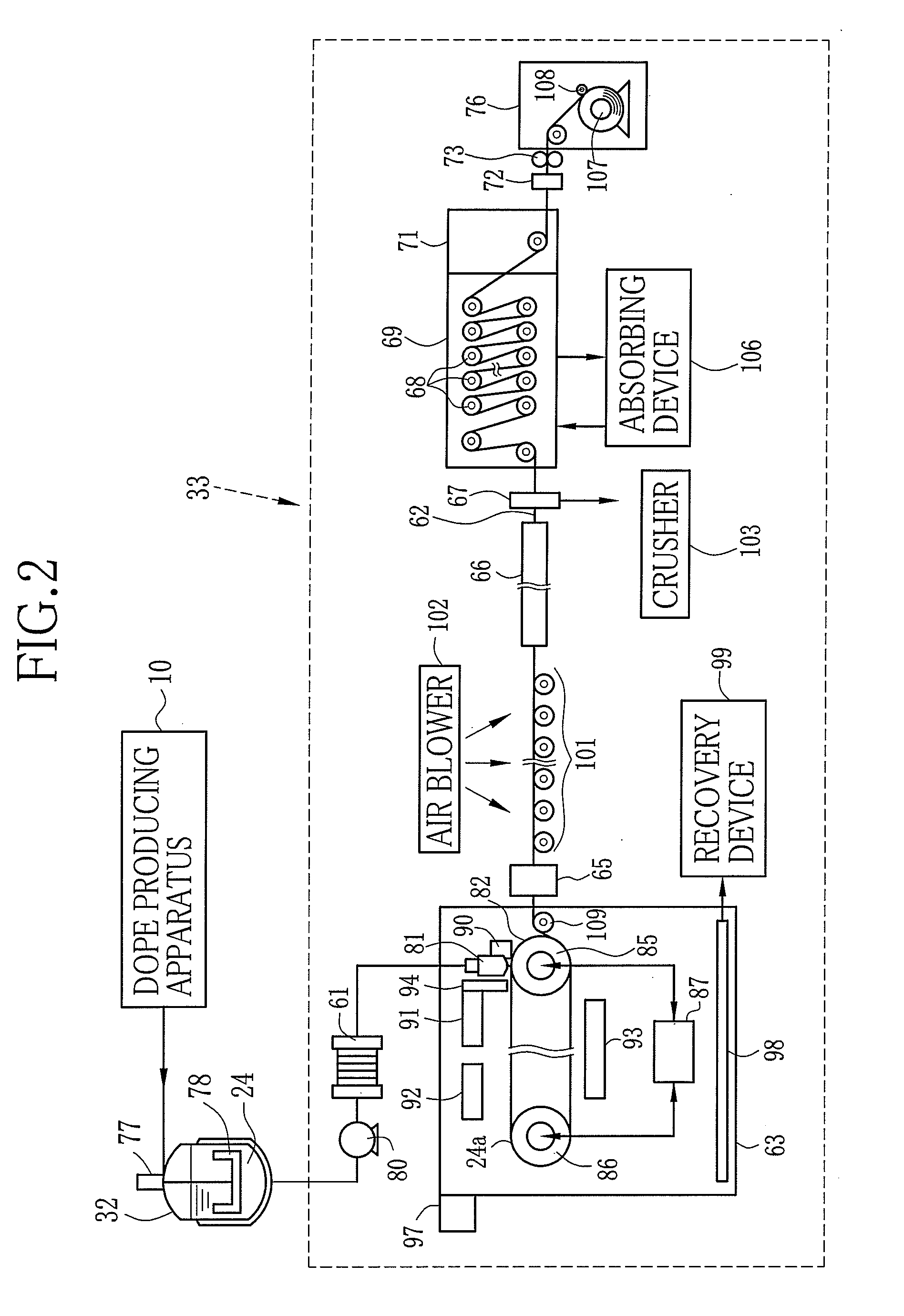
[0161]Instead of the first to third dopes 114 to 116 of Example 1, the above-noted first to third dopes 114 to 116 were used. The temperatures of the dry air from the air blowers 91, 92 and 93 were regulated to be 100° C. to 12...


PUM

PropertyMeasurementUnit
thicknessaaaaaaaaaa
thicknessaaaaaaaaaa
boiling pointaaaaaaaaaa

Abstract

First, second and third dopes (114, 115 and 116) containing a solid electrolyte are co-cast from a casting die (89) onto a running belt (82). The casting die (89) is provided with a feed block (119). A catalyst that promotes a redox reaction of electrodes in a fuel cell is added to the first dope (114) and the third dope (116). A casting membrane (112) having a three-layer structure is peeled from the belt (82) as a three-layered membrane (62) and sent to a tenter drier (64). In the tenter drier (64), the membrane (62) is dried in a state that both side edges thereof are held by clips, while stretched so as to have a predetermined width. The membrane (62) is then sent to a drying chamber (69) and the drying thereof is proceeded while supported by rollers.

Description

TECHNICAL FIELD[0001]The present invention relates to a solid electrolyte multilayer membrane, a method and an apparatus of producing the solid electrolyte multilayer membrane, and a membrane electrode assembly and a fuel cell using the solid electrolyte multilayer membrane. The present invention especially relates to a solid electrolyte multilayer membrane having excellent proton conductivity used for a fuel cell, a method and an apparatus of producing the solid electrolyte multilayer membrane, and a membrane electrode assembly and a fuel cell using the solid electrolyte multilayer membrane.BACKGROUND ART[0002]A lithium ion battery and a fuel cell that are used as a power source for portable devices have been actively studied in recent years. A solid electrolyte used for the above mentioned battery or cell is also actively studied. The solid electrolyte is, for instance, a lithium ion conducting material or a proton conducting material.[0003]The proton conducting material is genera...

Claims


Application Information

Patent Timeline
Patent Type & Authority Applications(United States)
IPC IPC(8): H01M8/10B29C41/28B28B5/02
CPCB01D67/0011Y02E60/50B01D67/0083B01D67/0095B01D71/42B01D71/68B01D71/82C08J5/2218H01M4/881H01M4/8857H01M4/921H01M4/926B01D2325/10B01D2325/26B01D67/0013B01D71/421
Inventor KAWANISHI, NAOYUKI
Owner FUJIFILM CORP
Learn More