
Hybrid Vehicle Having Engagable Clutch Assembly Coupled Between Engine And Traction Motor

a technology of clutch assembly and hybrid vehicle, which is applied in the direction of multiple dynamo-motor starters, dynamo-electric converter control, instruments, etc., can solve the problems of short driving distance, high fuel cost, and environmental pollution of motor vehicles that operate using only electric power

Active Publication Date: 2009-07-02
BYD CO LTD
View PDF18 Cites 70 Cited by
  • Summary
  • Abstract
  • Description
  • Claims
  • Application Information

AI Technical Summary

Benefits of technology

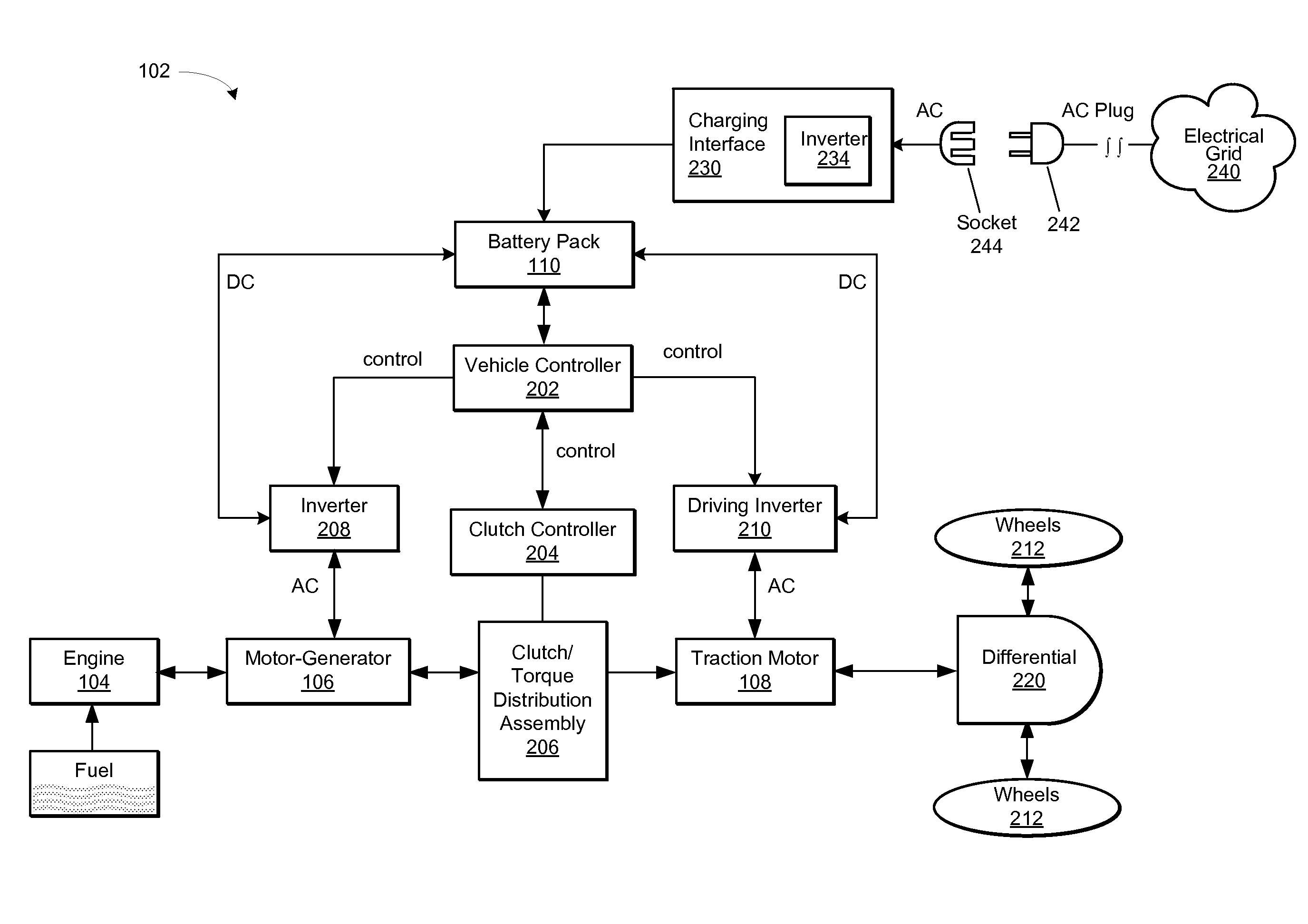
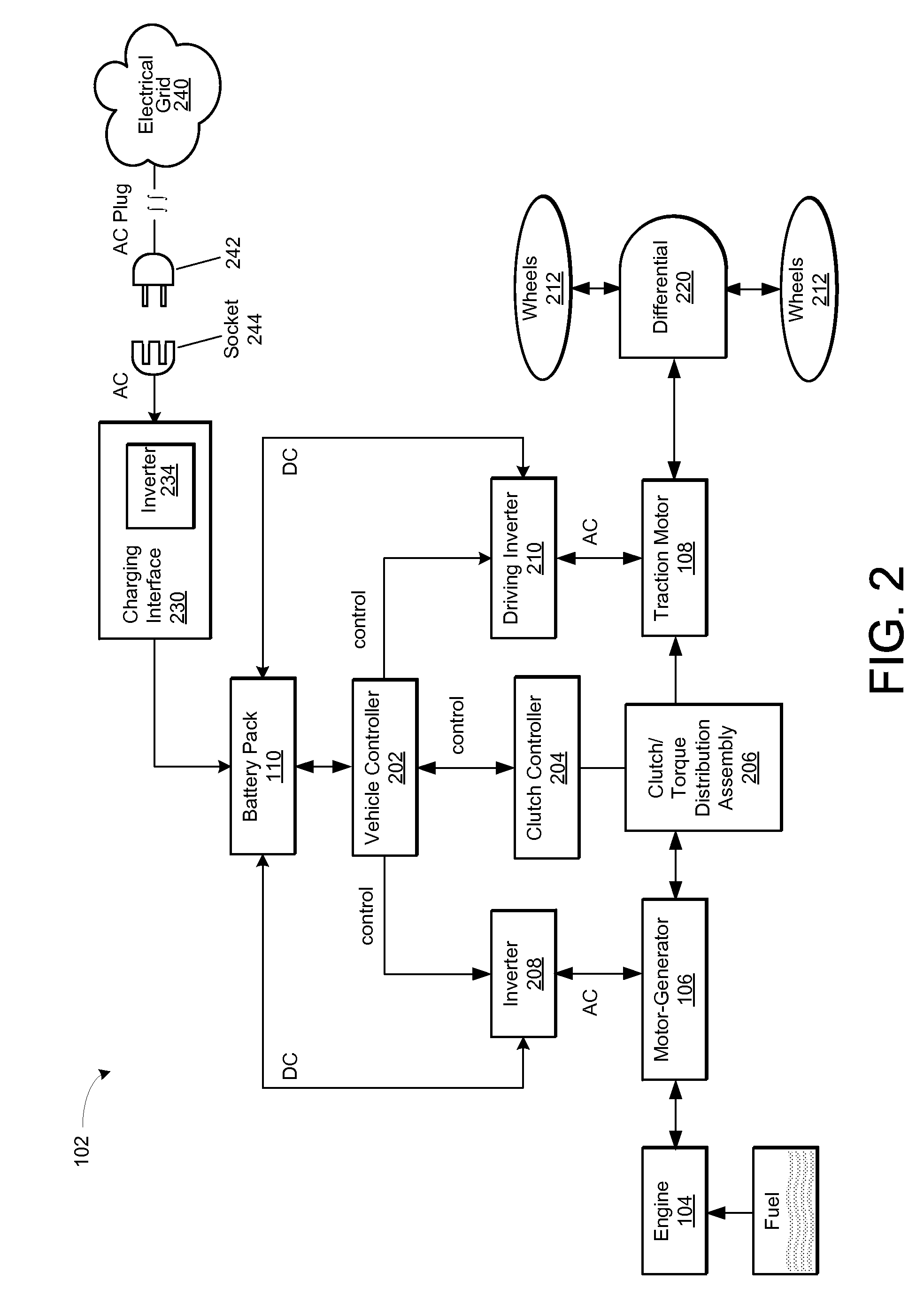
[0020]The hybrid power system may also include other system components, such as a vehicle controller, and a clutch or torsion distribution assembly. The clutch may selectively couple the internal combustible engine with the traction motor to charge the battery pack, operate the driving wheels, or both. The vehicle controller may change the operating mode of the hybrid power system depending on a variety of input signals. The torsion distribution assembly may also dampen any shock transmitted between the internal combustible engine and the motor-generator.
[0030]The engageable clutch assembly may operate in a first mechanical mode that selectively engages and disengages the internal combustion engine from the second motor / generator. The engageable clutch assembly may also operate in a second mechanical mode that dampens shock between the internal combustion engine and the first motor / generator when the internal combustion engine is not in angular alignment with the first motor / generator.

Problems solved by technology

Such fuels are expensive and contribute to environmental pollution.
However, motor vehicles that operate using only electric power have a short driving distance and do not address the needs of motor vehicle operators that often drive longer distances.
The torsion distribution assembly may also dampen any shock transmitted between the internal combustible engine and the motor-generator.

Method used


Image

  • Hybrid Vehicle Having Engagable Clutch Assembly Coupled Between Engine And Traction Motor
  • Hybrid Vehicle Having Engagable Clutch Assembly Coupled Between Engine And Traction Motor
  • Hybrid Vehicle Having Engagable Clutch Assembly Coupled Between Engine And Traction Motor

Examples


Embodiment Construction

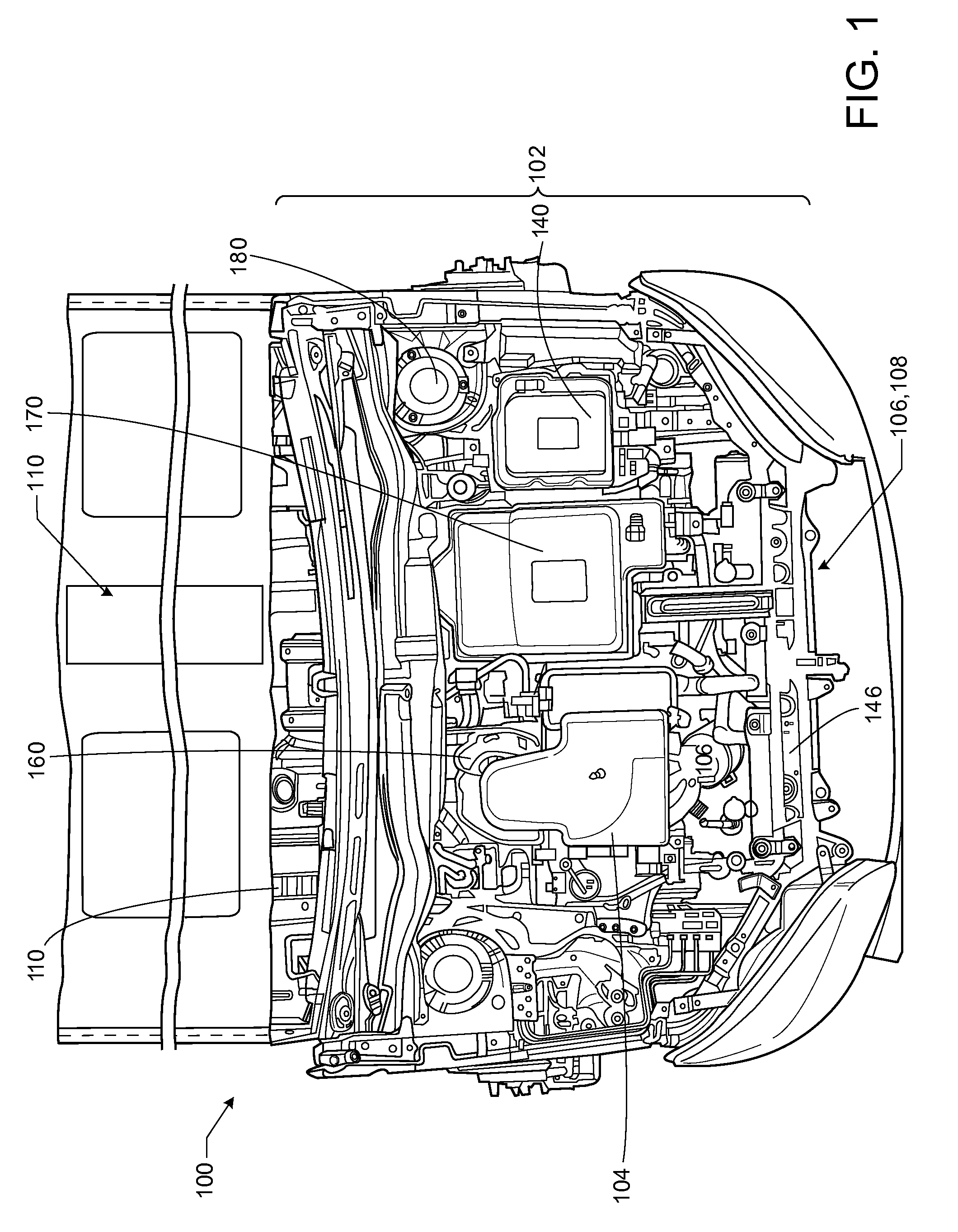
[0081]FIG. 1 shows the front engine compartment 100 of a motor vehicle equipped with a multi-mode hybrid power system 102. The hybrid power system 102 includes an internal combustible engine 104, an electric motor-generator 106, an electric traction motor 108, and a battery pack 110. The battery pack 110 may be located within a floorboard compartment and may not be visible in the view of FIG. 1. The hybrid power system 102 may also include other components, such as, a power inverter assembly 140, radiator 146, intake manifold 160, control system enclosure 170, shock absorber towers 180, and other components, such as, various filters, fuel injection system, master cylinder assembly, water pump, electronic ignition housing, etc.

[0082]FIG. 2 shows a block diagram of the multi-mode or hybrid power system 102, which includes a vehicle controller 202, a clutch controller 204, a clutch assembly or torque distribution assembly 206, a first inverter 208, a driving inverter 210, the engine 10...


PUM


Abstract

A hybrid vehicle includes a battery system, an internal combustion engine, a first motor / generator, a second motor / generator, and an engageable clutch assembly. The engageable clutch assembly is disposed between the internal combustion engine and the first motor / generator. When engaged, the engageable clutch assembly couples the rotor spindle of the second motor / generator with the hollow rotor shaft of the first motor / generator. The engageable clutch assembly may also operate in a first mechanical mode that selectively engages and disengages the internal combustion engine from the second motor / generator, or operate in a second mechanical mode that dampens shock between the internal combustion engine and the first motor / generator when the international combustion engine operates at a rotational speed that is different than a rotational of the first motor / generator.

Description

CROSS-REFERENCE TO RELATED APPLICATIONS[0001]This application claims the benefit of priority to the following applications:[0002]1) Chinese Patent Application No. 2008-10185948.3 (docket no. ______) filed on Dec. 13, 2008, entitled “______,”[0003]2) Chinese Patent Application No. 2008-10185949.8 (docket no. ______) filed on Dec. 13, 2008, entitled “______,”[0004]3) Chinese Patent Application No. 2008-10185950.0 (docket no. ______) filed on Dec. 13, 2008, entitled “______,”[0005]4) Chinese Patent Application No. 2008-10185951.5 (docket no. ______) filed on Dec. 13, 2008, entitled “______,”[0006]5) Chinese Patent Application No. 2008-10185952.X (docket no. ______) filed on Dec. 13, 2008, entitled “______,”[0007]6) Chinese Patent Application No. 2008-10217019.6 (docket no. 081484) filed on Oct. 11, 2008, entitled “A Hybrid Power Driving System and its Control Method,”[0008]7) Chinese Patent Application No. 2008-10217015.8 (docket no. 081322) filed on Oct. 11, 2008, entitled “A Hybrid P...

Claims


Application Information

Patent Timeline
IPC IPC(8): B60K6/38B60W10/02B60W10/10B60W20/00G06F17/00B60L50/10
CPCB60K1/02Y10S903/912B60K6/405B60K6/442B60L2240/421B60L2240/441B60W10/02B60W10/06B60W10/08B60W10/26B60W20/00B60W2510/0638B60W2510/081F16D3/66F16D48/02Y02T10/6234Y02T10/6269Y02T10/6286Y02T10/642Y10S903/946B60K6/387F16D2500/1024F16D2500/1066F16D2500/3024F16D2500/30401F16D2500/7027F16D2500/70406F16D2500/7041Y02T10/62Y02T10/64B60W20/40
Inventor LUO, HONGBINREN, YIYANG, SHENGLINWANG, TAOLIU, YAN
Owner BYD CO LTD
Learn More