
Catalyzed soot filter and method(s) to make these

a technology of catalytic soot and filter, which is applied in the direction of metal/metal-oxide/metal-hydroxide catalyst, machine/engine, etc., can solve the problems of short life time, large amount of expensive noble metal catalyst and/or rare earth oxide, etc., and achieves excellent soot combustion, rapid alkali volatilization, and long life.

Inactive Publication Date: 2009-06-25
DOW GLOBAL TECH LLC
View PDF52 Cites 8 Cited by
  • Summary
  • Abstract
  • Description
  • Claims
  • Application Information

AI Technical Summary

Benefits of technology

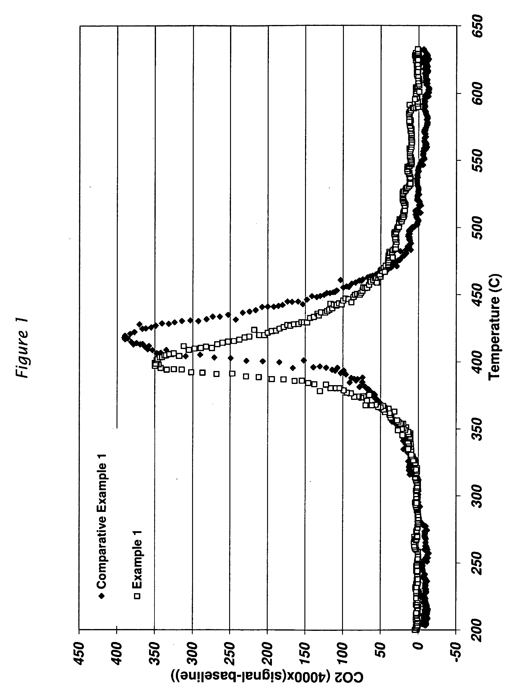
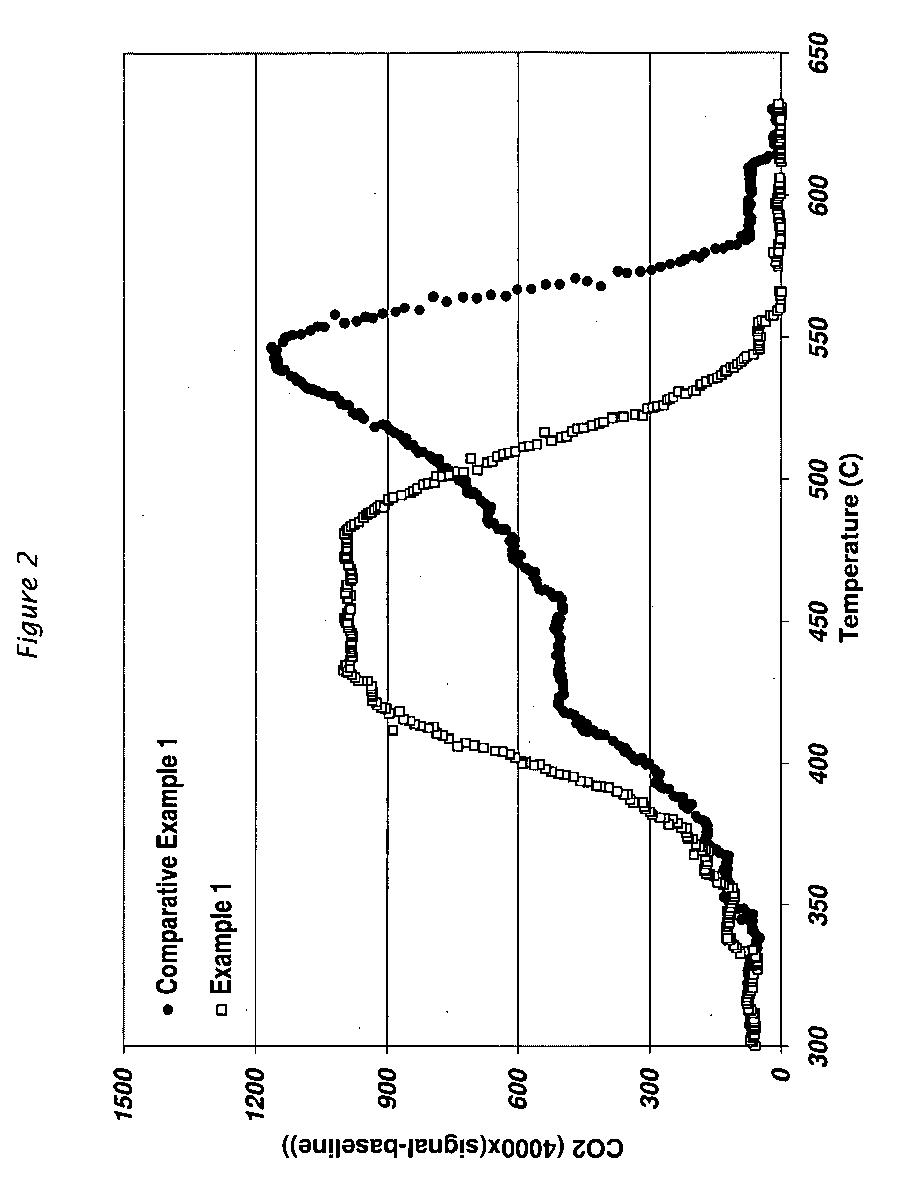
[0008]A first aspect of this invention is a catalyzed soot filter comprising a porous ceramic having, on at least a portion of the porous ceramic, a soot catalyst comprised of an alkali compound that is at least partially coated with a ceramic coating comprised of C bonded to a metal, semimetallic element or combination thereof. Surprisingly, the catalyzed soot filter displays excellent soot combustion, long lifetimes without either rapid alkali volatilization or attack of the porous ceramic as is common with alkali oxide catalysts. This is particularly surprising, since the coating ceramic contains carbon, which is catalyzed by the alkali catalyst, all the while the catalytic effect is not diminished appreciably, if at all, compared to an alkali catalyst not similarly coated.

Problems solved by technology

Diesel engines, because of the way they operate, emit soot particles or very fine droplets of condensate or a conglomerate of the two (particulates) as well as typical harmful gasoline engine exhausts (i.e., HC and CO).
Unfortunately, these catalyst are generally volatile and / or destructive to the filters resulting in impractical short life times. In addition, these catalysts still have required substantial amounts of noble metal catalysts to reduce the HC and CO gases that are emitted along with the Diesel soot.
Unfortunately, these catalysts have tended to required substantial amounts of expensive noble metal catalysts and / or rare earth oxides.

Method used


Image

  • Catalyzed soot filter and method(s) to make these
  • Catalyzed soot filter and method(s) to make these

Examples


example 1

[0050]A 0.75″ (1.9 cm)×0.75″ (1.9 cm)×3″ (7.6 cm) acicular mullite (ACM) Diesel particulate filter (DPF) (200 cells / in2) made in the same manner as described as described by Example 4 of WO 03 / 082773A1 (including heat treating to 1400° C. as also described in Example 4 of WO 03 / 082773A1), was coated with cesium silicate catalyst (4SiO2:Cs2O) by applying 6-5 ml of a freshly prepared precursor solution composed of 8.974 g Ludox TMA 34 wt % silica, 9.747 g 50 wt % Cesium acetate solution, 0.10 g 50 wt % citric acid solution and 6.364 g water to the DPF. The solution gelled in 1 to 2 hours at room temperature. The DPF was dried overnight at 120° C. then calcined in air at 700° C. for 1 h to form an alkali coated catalyst DPF.

[0051]A silicon carbide layer was applied to the the alkali catalyst coated DPF as follows. Approximately 7 mL of a solution of 5 parts toluene to 1 parts allylhydridopolycarbosilane SP matrix polymer-Var. 10, (Starfire Systems Inc., 877 25th Street Watervliet N.Y. ...


PUM

PropertyMeasurementUnit
Temperatureaaaaaaaaaa
Fractionaaaaaaaaaa
Fractionaaaaaaaaaa

Abstract

An improved soot catalyst is comprised of an alkali compound at least partially coated by a ceramic coating comprised of C bonded to a metal, semimetallic element or combination thereof. The improved soot catalyst may be employed in catalyzed Diesel particulate filters. In one method to make a catalyzed Diesel particulate filter, the improved filter is made by contacting a porous ceramic body having an alkali catalyst thereon, coating the alkali catalyst with an organic ceramic precursor, heating the ceramic body to a temperature in an atmosphere sufficient to decompose the organic ceramic precursor to form the soot catalyst on the porous ceramic body without volatilizing substantial amount of the alkali catalyst away.

Description

CROSS-REFERENCE TO RELATED APPLICATION[0001]This application claims the benefit of U.S. Provisional Application Ser. No. 61 / 015,941 filed Dec. 21, 2007 which is hereby incorporated by reference.FIELD OF THE INVENTION[0002]The present invention relates to an improved catalyzed particulate filter.BACKGROUND OF THE INVENTION[0003]Diesel engines, because of the way they operate, emit soot particles or very fine droplets of condensate or a conglomerate of the two (particulates) as well as typical harmful gasoline engine exhausts (i.e., HC and CO). These “particulates” (herein Diesel soot), are rich in condensed, polynuclear hydrocarbons, some of which may be carcinogenic.[0004]As the awareness of the danger Diesel soot presents to health collides with the need for greater fuel efficiency that Diesel engines provide, regulations have been enacted curbing the amount of Diesel soot permitted to be emitted. To meet these challenges, soot filters have been used. When using such a filter, the ...

Claims


Application Information

Patent Timeline
IPC IPC(8): B01J27/224
CPCB01D53/944Y10S55/10B01D2255/20715B01D2255/20723B01D2255/2073B01D2255/20753B01D2255/20769B01D2255/20776B01D2258/012B01J23/04B01J27/22B01J27/224B01J37/084Y10S55/05Y10S55/30B01D2255/20707
Inventor NILSSON, ROBERT T.ZIEBARTH, ROBINMARTIN, STEVEN J.
Owner DOW GLOBAL TECH LLC
Learn More