
Phosphor and production method of the same and light source and LED using the phosphor

a technology of phosphor and light source, which is applied in the direction of discharge tube/lamp details, luminescent compositions, discharge tubes luminescent screens, etc., can solve the problem of not being able to produce yellow light emission with high efficiency, and achieve excellent oxidation resistance, long life, and high efficiency

Inactive Publication Date: 2005-11-17
DOWA ELECTRONICS MATERIALS CO LTD
View PDF34 Cites 65 Cited by
  • Summary
  • Abstract
  • Description
  • Claims
  • Application Information

AI Technical Summary

Benefits of technology

[0013] With respect to the above-described LED and light source which emit visible light or white light by a combination of a light emitting portion constituted of a light emitting element which emits light of the ultraviolet-blue wavelength by itself and a phosphor which has an excitation band corresponding to light of the ultraviolet-blue wavelength region generated from the light emitting portion and emits fluorescent light of a predetermined wavelength region, it is strongly demanded to improve not only the emission efficiency of the light emitting portion but also the emission efficiency of fluorescent light of the phosphor, in order to improve luminance of the visible light or white light. This is because the luminance of the entire white light source can be improved by the emission efficiency of the phosphor.
[0018] Accordingly, in order to improve the emission efficiency of the LED which emits white light, there have been demanded a phosphor having an excitation band corresponding to light of the ultraviolet-visible (300 to 550 nm) wavelength region and high emission efficiency, and a phosphor of the aforementioned type which further emits yellow to red fluorescent light.
[0019] The present invention is made in view of the above described situation, and an object thereof is to provide a phosphor having an excitation band corresponding to light of the ultraviolet-visible (300 to 550 nm) wavelength region emitted from a light emitting element which emits blue or ultraviolet light, the phosphor having high emission efficiency and further capable of emitting fluorescent light in a wide range of visible light.
[0020] As a result of study on host material compositions of various phosphors with respect to the above-described object, the inventors of the present invention devised a phosphor with higher efficiency and an excellent light emitting characteristic, which has a new host material composition that is easy to be produced.
[0038] The phosphor according to any one of the first to the eleventh aspect represented by the general formula Mn+pSi3Oa+qN4+r:Z has an excitation band corresponding to ultraviolet-green light (wavelength region from 300 to 550 nm) and emits light with high efficiency. Further, the phosphor does not include aluminum which is liable to be oxidized in a composition part that is a skeletal structure and excellent in oxidation resistance since it includes oxygen. Furthermore, the phosphor has a longer lifetime and is easy to be produced.
[0039] According to the twelfth aspect, the phosphor represented by the general formula Ma+pS3On+qN4+r:Z is produced using raw materials with high purity which are easy to be obtained, so that a high-performance phosphor can be produced at low cost.

Problems solved by technology

However, when the light emitting element in the LED emits ultraviolet light, it deviates from the excitation range of the phosphor, so that it cannot produce yellow light emission with high efficiency.

Method used


Image

  • Phosphor and production method of the same and light source and LED using the phosphor
  • Phosphor and production method of the same and light source and LED using the phosphor
  • Phosphor and production method of the same and light source and LED using the phosphor

Examples


example 1

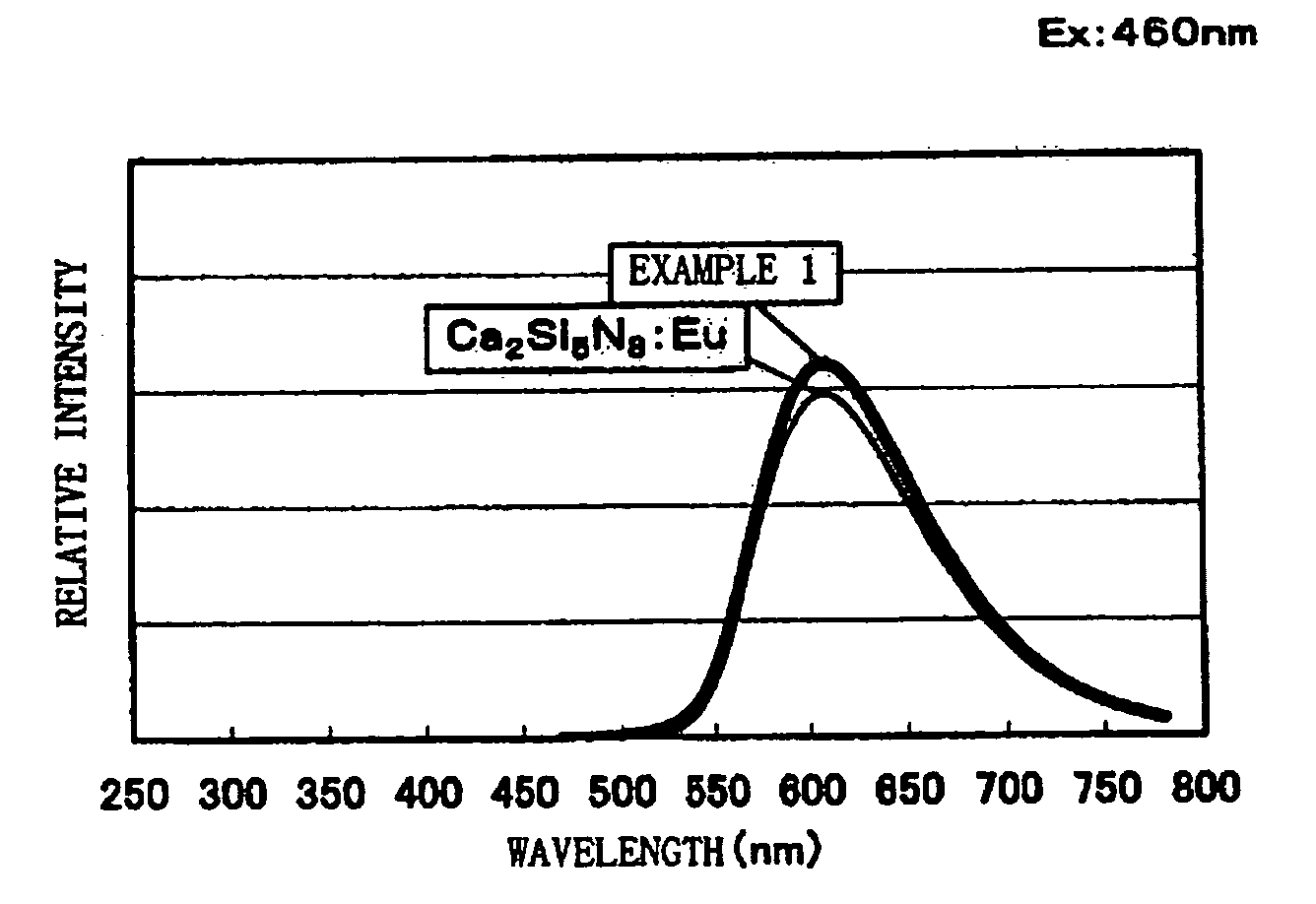
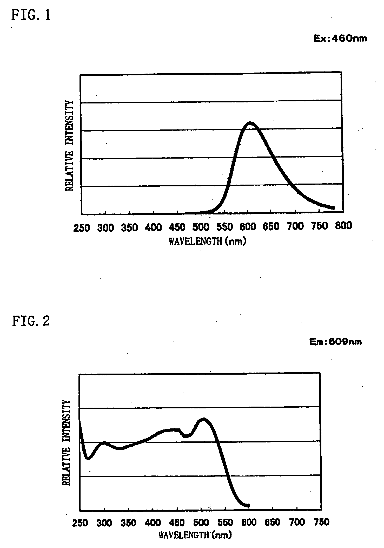
[0083] Commercially available CaO [3N], Si3N4 [3N], and Eu2O3 [3N] are prepared, and the respective raw materials are weighed so that a mol ratio of them becomes CaO:Si3N4:Eu2O3=1.4775:1:0.01125. These weighed raw materials were mixed using a mortar inside a glove box under a nitrogen atmosphere. The mixed raw materials were filled into a melting pot made of boron nitride, heated to 1600° C. by a heating rate of 15° C. / min under a nitrogen atmosphere, retained and fired at 1600° C. for three hours, and cooled down thereafter from 1600° C. to 200° C. for an hour to thereby obtain a phosphor sample. Results of chemical analysis and measurement results of an average particle size and a specific surface area of obtained phosphor powder are shown in Table 1. From the chemical analysis results, it was found that the composition formula of the phosphor sample is Ca1.58Si3O1.63N4.35:Eu0.024.

TABLE 1AverageSpecificCaSiEuNOparticlesurface(%)(%)(%)(%)(%)size (D50)area (m2 / g)Example 126.335.01...

examples 2 to 6

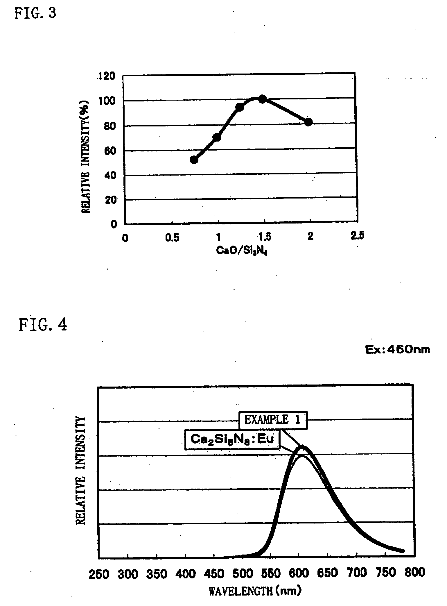
[0089] In Examples 2 to 6, phosphor samples were made and luminescence intensity was measured similarly to Example 1 except that the mixing ratio of the respective raw materials of CaO [3N], Si3N4 [3N], and Eu2O3 [3N] explained in Example 1 was changed and set as Examples 2 to 6.

[0090] Here, in Example 2, CaO:Si3N4:Eu2O3=0.073875:1:0.005625 was set, in Example 3, CaO:Si3N4:Eu2O3=0.985:1:0.0075 was set, in Example 4, CaO:Si3N4:Eu2O3=1.23125:1:0.009375 was set, in Example 5, CaO:Si3N4:Eu2O3=1.4775:1:0.01125 was set, and in Example 6, CaO:Si3N4:Eu2O3=1.97:1:0.015 was set.

[0091] Measurement results of luminescence intensity of the phosphor samples according to Examples 2 to 6 are explained with reference to FIG. 3. Here, in FIG. 3, luminescence intensity of the phosphor sample is taken on the vertical axis, and a value of CaO / Si3N4, which is the raw material ratio, is taken on the horizontal axis. Note that the luminescence intensity of the phosphor samples is standardized by luminesc...

example 7

[0094] An LED of ultraviolet light having a nitride semiconductor as a light emitting portion was used, the phosphor sample obtained in Example 2, a commercially available blue phosphor (BAM:Eu), and a commercially available green phosphor (ZnS:Cu, Al) were applied on the LED, and the LED of ultraviolet light was illuminated. Then, the respective phosphors emitted light by light from the LED, and an LED which emits white light when visually observed was obtained.

[0095] Further, on an LED of blue light having a nitride semiconductor as a light emitting portion, the phosphor sample obtained by the present invention and a commercially available yellow phosphor (YAG:Ce) were applied, and the LED of blue light was illuminated. Then, the respective phosphors emitted light by light from the LED, and an LED which emits white light when visually observed was obtained.


PUM

PropertyMeasurementUnit
particle sizeaaaaaaaaaa
wavelengthaaaaaaaaaa

Abstract

A phosphor with high efficiency having an excitation band corresponding to light of the ultraviolet-visible (300 to 550 nm) wavelength region emitted from a light emitting element which emits blue or ultraviolet light is provided. Commercially available CaO [3N], Si3N4 [3N], and Eu2O3 [3N] are prepared, respective materials are weighed and mixed to have a mol ratio of CaO:Si3N4:Eu2O3=1.4775:1:0.01125, and then the mixture is heated to 1600° C. by a heating rate of 15° C. / min under a nitrogen atmosphere and retained and fired at 1600° C. for three hours. Thereafter, the raw materials are cooled down from 1600° C. to 200° C. for an hour to thereby produce a phosphor having a composition formula Ca1.58Si3O1.63N4.35:Eu0.024.

Description

BACKGROUND OF THE INVENTION [0001] 1. Field of the Invention [0002] The present invention relates to a phosphor used in a display device such as an LED, CRT, PDP, FED, and EL, and a lighting unit such as a vacuum fluorescent display and fluorescent lamp. More particularly, the present invention relates to a phosphor and a production method of the same, the phosphor being suitable for an LED, a light source, a lighting unit and the like each of which has a light emitting portion and a phosphor of ultraviolet-blue light or the like and emits visible light or white light by cooperation of both the light emitting portion and the phosphor, and to a light is source and an LED using the phosphor. [0003] 2. Description of the Related Art [0004] An LED, a light source and a lighting unit are known, which emit white light by a combination of a light emitting portion constituted of a light emitting element which emits blue or ultraviolet light by itself and a phosphor which has an excitation b...

Claims


Application Information

Patent Timeline
Patent Type & Authority Applications(United States)
IPC IPC(8): C09K11/59C09K11/08C09K11/77H01L33/32H01L33/50H05B33/14
CPCC09K11/0838H01L33/502C09K11/7734C09K11/77347
Inventor GOTOH, MASAHIRONAGATOMI, AKIRASAKANE, KENJIYAMASHITA, SHUJI
Owner DOWA ELECTRONICS MATERIALS CO LTD
Learn More