
Method for manufacturing semiconductor device

a semiconductor and manufacturing technology, applied in the direction of semiconductor devices, radio-controlled devices, electrical equipment, etc., can solve the problems of ehps (electron hole pairs), ccd image sensors may not be highly integrated, and surface defects in semiconductor substrates, so as to improve the characteristics of image sensors and improve the device characteristics of cmos image sensors

Inactive Publication Date: 2009-06-25
DONGBU HITEK CO LTD
View PDF6 Cites 1 Cited by
  • Summary
  • Abstract
  • Description
  • Claims
  • Application Information

AI Technical Summary

Benefits of technology

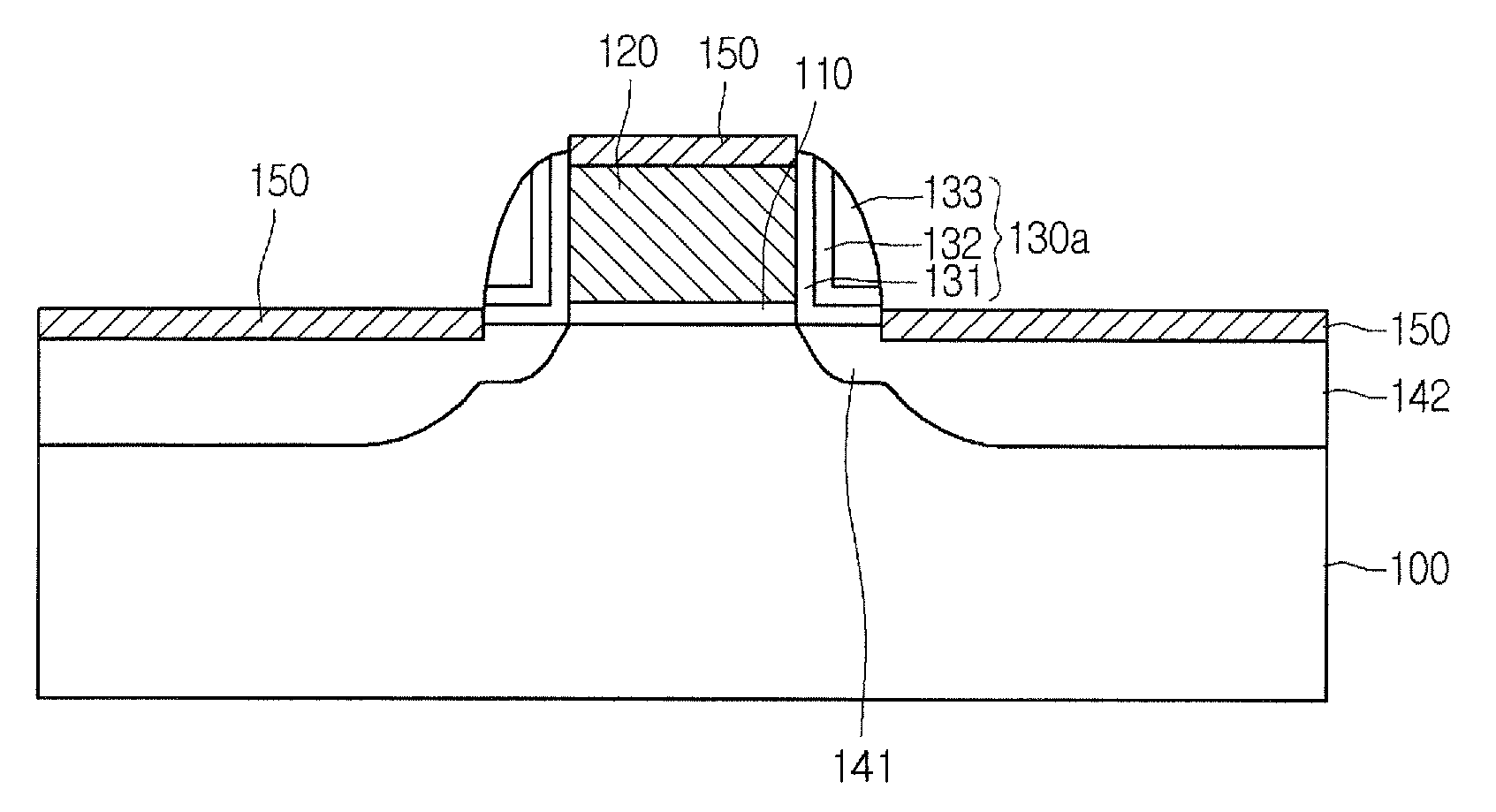
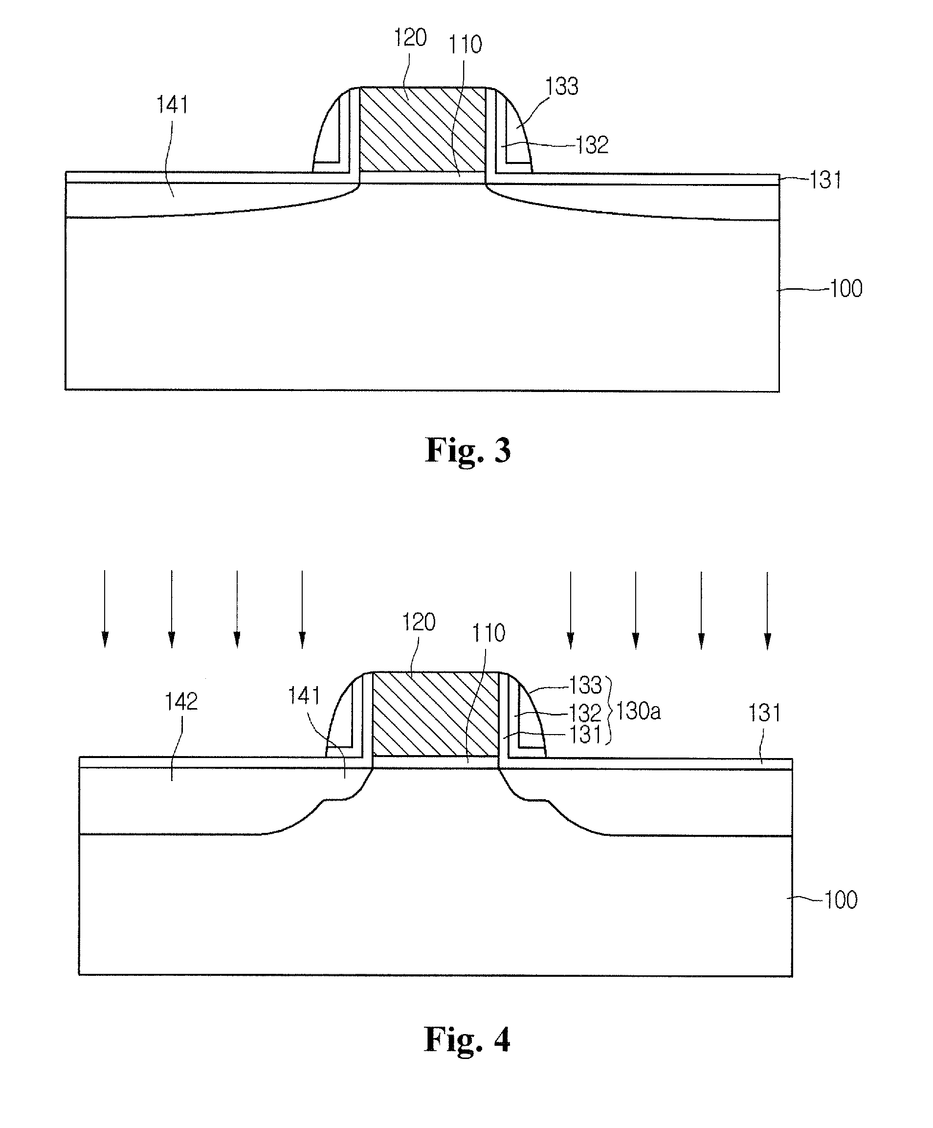
[0008]An embodiment of the present invention provides a method for manufacturing a semiconductor device, which can inhibit plasma damage and current leakage from occurring by forming a remaining oxide layer after performing dry and wet etching processes when forming a gate spacer of the semiconductor device.
[0011]According to an embodiment, when forming a gate spacer in the semiconductor device, an oxide layer is formed to remain on source and drain regions to inhibit plasma damage and current leakage from occurring during an ion implantation process, thereby improving device characteristics of a CMOS image sensor.
[0012]Further, according to an embodiment, current leakage of a driving transistor of an image sensor can be inhibited from occurring, so that characteristics of an image sensor can be improved.

Problems solved by technology

Further, since the CCD image sensor requires an additional support circuit for adjusting an image signal or generating standard video output, the CCD image sensor may not be highly integrated.
In the transistor used for driving the conventional CMOS image sensor, when directly implanting high concentration impurities into a semiconductor substrate in order to form source and drain regions for the transistor, surface defects may occur in the semiconductor substrate.
The surface defects may cause generation of EHPs (electron-hole pairs).
Thus, although light is not incident from an exterior, dark current may occur and the image sensor may abnormally operate, causing defect of the image sensor.

Method used


Image

  • Method for manufacturing semiconductor device
  • Method for manufacturing semiconductor device
  • Method for manufacturing semiconductor device

Examples


Embodiment Construction

[0014]Hereinafter, a method for manufacturing a semiconductor device according to an embodiment will be described in detail with reference to the accompanying drawings. The size (dimension) of elements shown in the drawings may be magnified for the purpose of clear explanation and the real size of the elements may be different from the size of elements shown in drawings. In addition, the present invention may not include all the elements shown in the drawings and may not be limited thereto. The elements except for essential elements of the present invention can be omitted or added without limitation.

[0015]In the description of embodiments, it will be understood that when a layer (or film) is referred to as being ‘on / above / over / upper’ another layer or substrate, it can be directly on another layer or substrate, or intervening layers may also be present. Further, it will be understood that when a layer is referred to as being ‘down / below / under / lower’ another layer, it can be directly ...


PUM


Abstract

Disclosed are methods for manufacturing a semiconductor device. One method includes the steps of forming a gate electrode on a semiconductor substrate, sequentially forming a first oxide layer, a nitride layer and a second oxide layer on the semiconductor substrate including the gate electrode, dry-etching the second oxide layer, wet-etching the nitride layer, and forming source and drain regions at sides of the gate electrode by implanting ions into the semiconductor substrate on which the first oxide layer is formed. According to the method, in the process of forming a gate spacer in the semiconductor device, an oxide layer of the gate spacer remains on the source and drain regions, and then an ion implantation process is performed, so that plasma damage and current leakage can be inhibited from occurring in the source and drain regions. Thus, device characteristics of a CMOS image sensor can be improved.

Description

CROSS-REFERENCE TO RELATED APPLICATION[0001]The present application claims the benefit under 35 U.S.C. § 119 of Korean Patent Application No. 10-2007-0135987, filed Dec. 24, 2007, which is hereby incorporated by reference in its entirety.BACKGROUND[0002]In general, an image sensor is a semiconductor device that converts an optical image into electrical signals. The image sensor is typically classified as a Charge Coupled Device (CCD) image sensor, in which individual Metal Oxide Semiconductor (MOS) capacitors are located closely to each other such that charge carriers are stored in or discharged from the capacitors, or a CMOS image sensor employing a switching mode to sequentially detect output by providing MOS transistors corresponding to the number of pixels through a CMOS technology that uses peripheral devices, such as a control circuit and a signal processing circuit.[0003]The CCD image sensor requires high power consumption in order to obtain permissible charge transfer effici...

Claims


Application Information

Patent Timeline
IPC IPC(8): H01L21/336
CPCH01L27/14603H01L29/665H01L27/14612H01L29/6659H01L29/7833H01L29/6656H01L21/18H01L21/24H01L27/146
Inventor JUNG, CHUNG KYUNG
Owner DONGBU HITEK CO LTD
Learn More