
Magnetic Member, Rotor and Motor

a rotor and magnetic member technology, applied in the direction of rotating magnets, synchronous machines with stationary armatures, dynamo-electric machines, etc., can solve the problems of vibration and noise, unfavorable supply of skews, and different magnetic fluxes between the magnetic poles, so as to reduce the ripple effect of torqu

Inactive Publication Date: 2009-06-18
DAIKIN IND LTD
View PDF2 Cites 14 Cited by
  • Summary
  • Abstract
  • Description
  • Claims
  • Application Information

AI Technical Summary

Benefits of technology

[0015]The present invention has an object to avoid the absolute necessity of the asymmetry of configuration of a rotor, avoid the necessity to depress the outer surface and further reduce the torque ripple.

Problems solved by technology

In terms of productivity, however, providing skews is not desirable.
This causes magnetic fluxes to flow in a different manner between the magnetic poles, which is not desirable in terms of occurrence of vibrations and noise.
In Patent document 4, since the thickness of a bridge is thin in the vicinity of the border between the magnetic poles, the difference in thickness of the magnetic member in the radial direction between the border of the magnetic poles and the center of the magnetic poles is not reduced, which does not lead to sufficient reduction of torque ripple.
In addition, a mode of depressing the outer surface of the rotor is also illustrated, however, this configuration is not desirable in terms of occurrence of windage loss or wind noise.
The techniques introduced in Patent documents 5 and 6 do not absolutely require the asymmetry of configuration of the rotor or do not need to depress the outer surface, however, the difference in thickness of the magnetic member in the radial direction between the border of the magnetic poles of the rotor and the center of magnetic poles is not reduced, which still does not lead to sufficient reduction of torque ripple.

Method used


Image

  • Magnetic Member, Rotor and Motor
  • Magnetic Member, Rotor and Motor
  • Magnetic Member, Rotor and Motor

Examples


first embodiment

Description of Basic Configuration

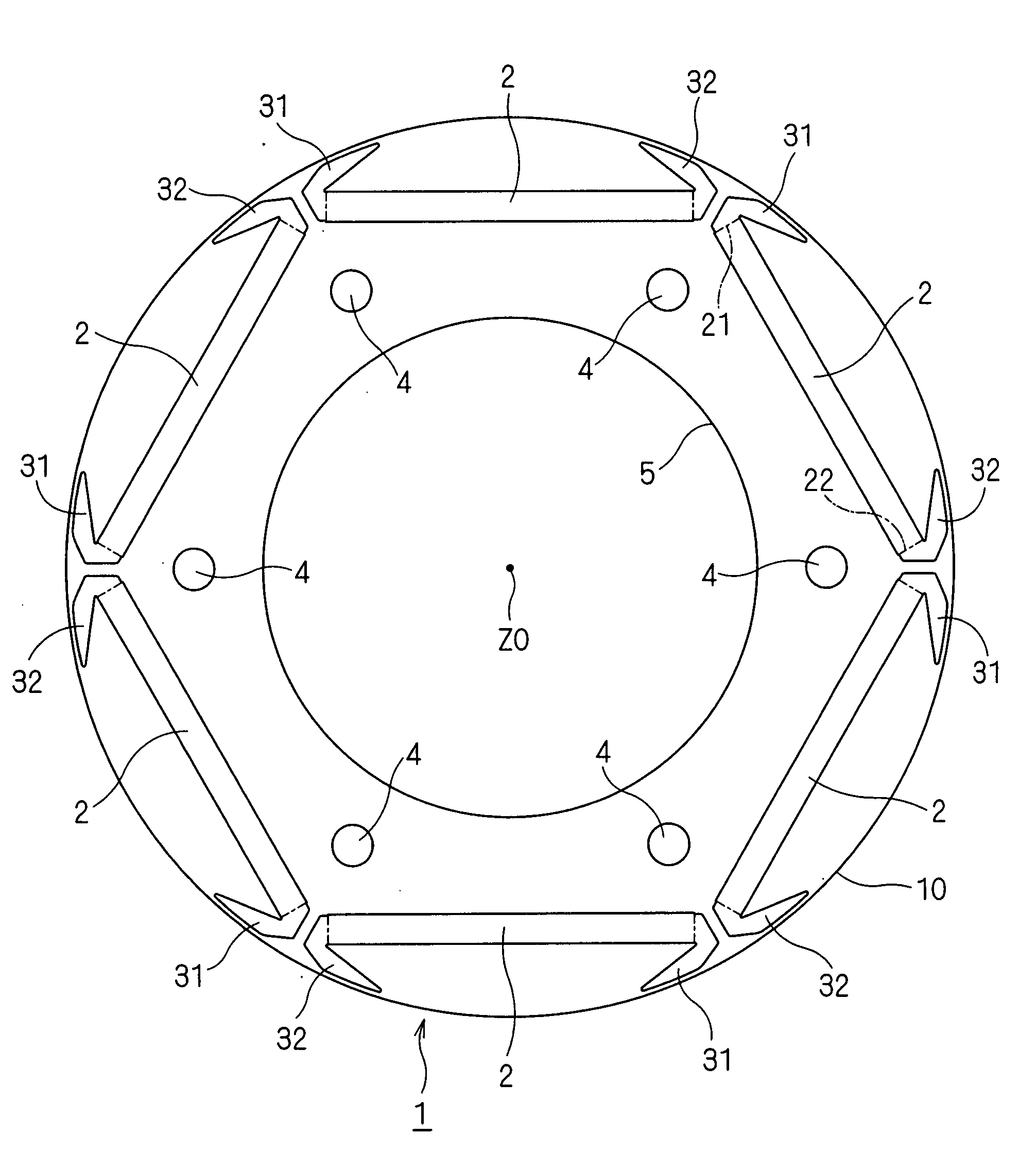
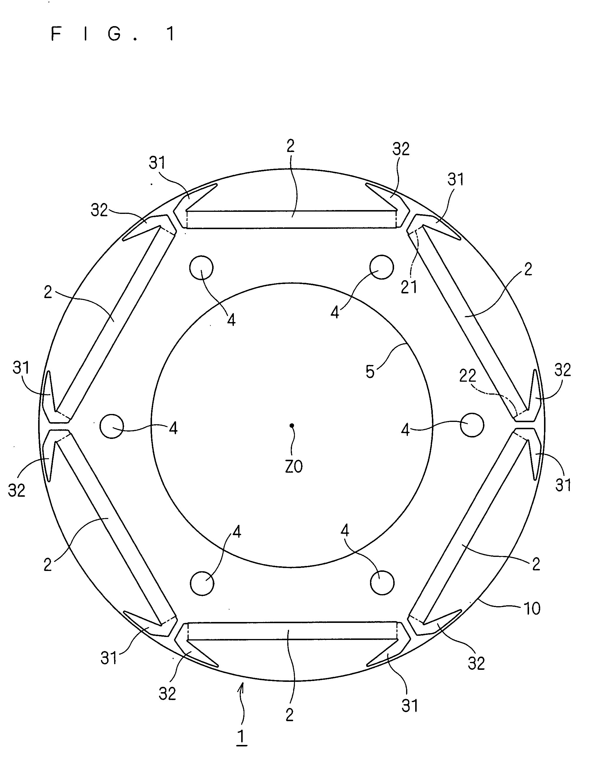
[0068]FIG. 1 is a plan view showing the structure of a magnetic member 1 according to a first embodiment of the present invention. The magnetic member 1 can contribute to an embedded magnet type rotor, as will be described later. The magnetic member 1 may extend in the direction perpendicular to the sheet of drawing, or may be thin in the direction perpendicular to the sheet of drawing. In the former case, it may be formed of, for example, iron dust core to be employed as the core of a rotor. In the latter case, it may be formed employing, for example, steel sheets, which are stacked one upon another to be employed as the core of a rotor. In that case, FIG. 1 can be understood as a sectional view of that core. The center Z0 corresponds to a rotation axis of the core of the rotor.

[0069]The magnetic member 1 has a periphery 10 showing an annular shape, and the case in which the periphery 10 shows a circle as an outer periphery is illustrated here. How...

second embodiment

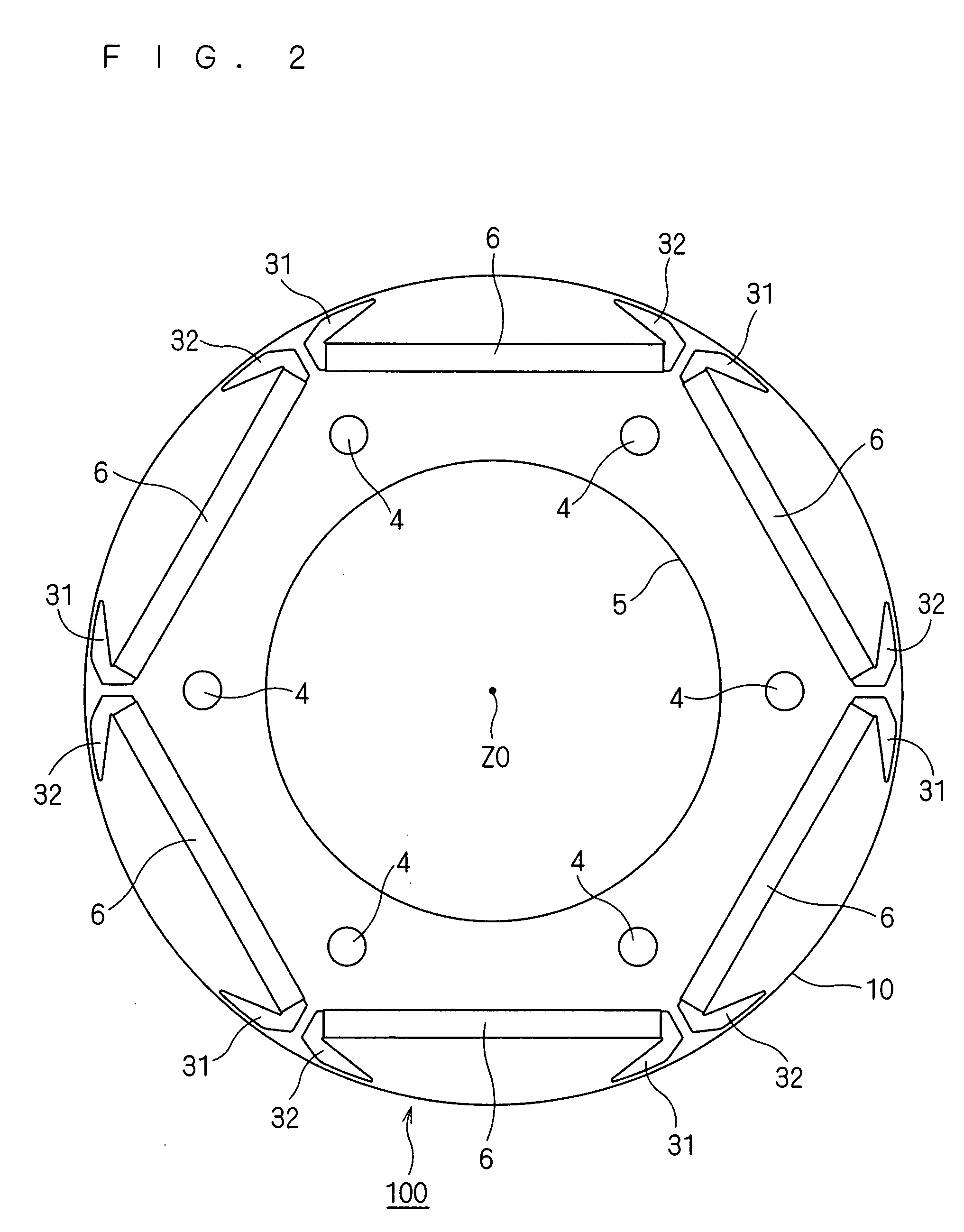
[0125]FIG. 20 is a sectional view partially showing the structure of a rotor 100 according to a second embodiment of the present invention. Of course, a structure in which the field magnets 6 are omitted from that rotor 100 can be understood as the magnetic member 1 according to the present invention.

[0126]The rotor 100 in the present embodiment features changing the distance between the second portions 312, 322 and periphery 10 in a curve in the circumferential direction, and is similar to the technique described in the first embodiment except this point. Also with such structure, the magnetic member is increased in thickness in the vicinity of the border of magnetic poles of the rotor explained in the first embodiment, so that the difference in thickness of the magnetic member in the radial direction between the border and center of magnetic poles can be reduced. The torque ripple can thereby be reduced, similarly to the first embodiment. Of course, the asymmetry of the configurat...

third embodiment

[0127]FIG. 21 is a sectional view partially showing the structure of a rotor 100 according to a third embodiment of the present invention. Of course, a structure in which the field magnets 6 are omitted from that rotor 100 can be understood as the magnetic member 1 according to the present invention.

[0128]The rotor 100 in the present embodiment features communicating a pair of third portions 313 and 323 adjacent to each other respectively belonging to adjacent field magnet through-holes 2, and is similar to the technique described in the first embodiment except this point. Also with such structure, it is apparent that the operations and effects explained in the first embodiment can be obtained. Further, in the structure shown in the second embodiment, the third portions 313 and 323 may be communicated with each other.

[0129]However, it is desirable that the third portions 313 and 323 be adjacent separately in terms of mechanical strength in the vicinity of the gaps 31 and 32, that is...


PUM


Abstract

In the present invention, since gaps respectively provided at one ends of a field magnet through-hole respectively extend toward the other ends passing on the side of a periphery with respect to the field magnet through-hole, the radial dimension of the magnetic member in this portion can be made smaller than the center of magnetic poles, so that the difference in thickness of the magnetic member in the radial direction between the border of magnetic poles and the magnetic poles can be reduced. Accordingly, the asymmetry of the configuration of a rotor is not absolutely necessary, and the outer surface does not need to be depressed for reducing the torque ripple.

Description

TECHNICAL FIELD[0001]This invention relates to a motor, particularly to the structure of a rotor.BACKGROUND ART[0002]The technique for reducing the torque ripple of a motor has conventionally been proposed. For instance, various devices are disclosed in the following patent documents.[0003]Patent document 1 discloses a technique for providing skews in a rotor, and Patent document 2 discloses a technique for providing skews in a stator. In terms of productivity, however, providing skews is not desirable.[0004]Patent document 3 focuses attention to the configuration of magnetic flux barrier present between magnetic poles of a rotor, and intends to reduce the torque ripple by setting the angle it makes at a predetermined value or at an unequal pitch.[0005]Patent document 4 illustrates a technique for varying the thickness of a bridge present between a magnetic barrier of a rotor and an outer periphery, Patent document 5 illustrates a technique for setting the angle of magnetic poles of...

Claims


Application Information

Patent Timeline
IPC IPC(8): H02K21/16
CPCH02K29/03H02K1/276
Inventor NISHIJIMA, KIYOTAKA
Owner DAIKIN IND LTD
Learn More