
Crankcase ventilation filter/pre-separator

a technology of pre-separator and crankcase, which is applied in the direction of combustion-air/fuel-air treatment, separation process, liquid degasification, etc., can solve the problems of internal engine contamination and efficiency loss, fouling expensive components, and contaminated beer with oil mist, so as to facilitate the return to the engine, easy assembly and easy attachment

Inactive Publication Date: 2009-06-18
PARKER HANNIFIN CORP
View PDF11 Cites 5 Cited by
  • Summary
  • Abstract
  • Description
  • Claims
  • Application Information

AI Technical Summary

Benefits of technology

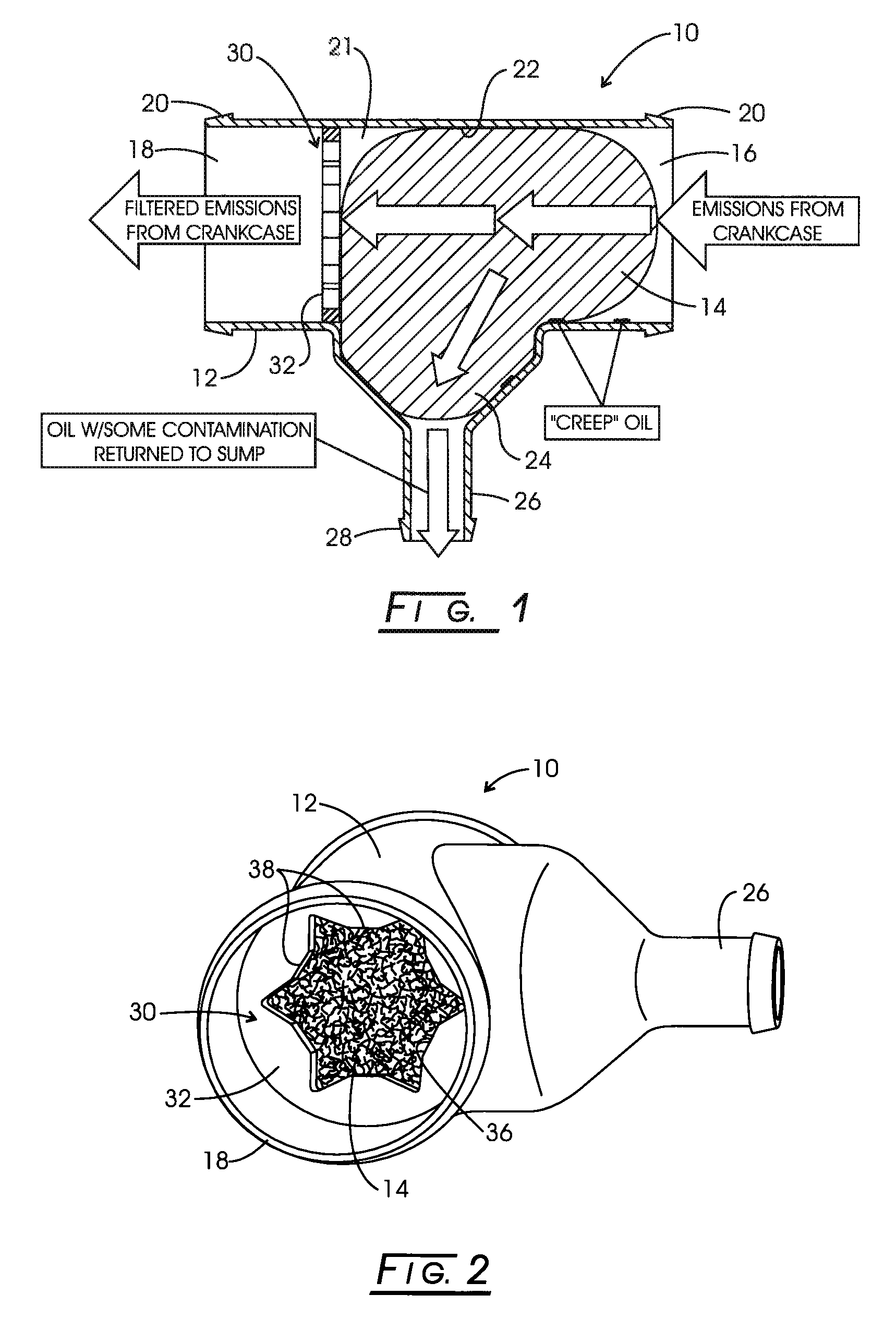
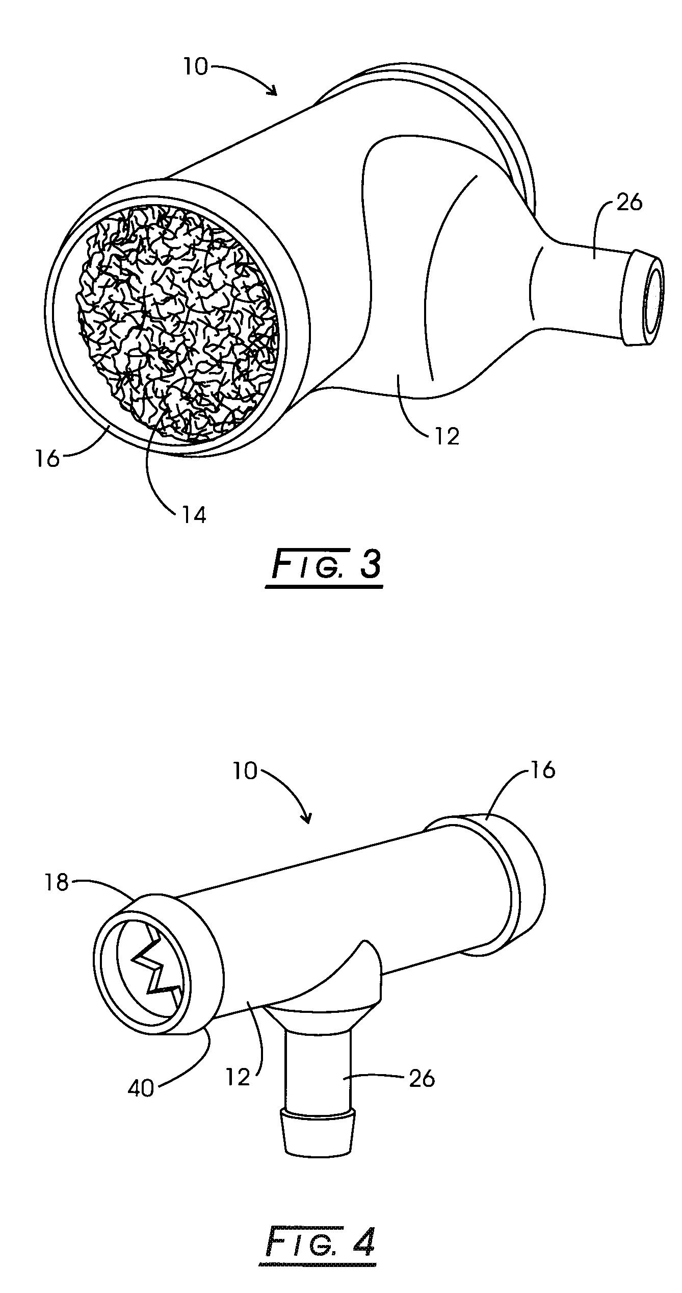
[0011]The present invention provides a novel and unique crankcase emissions control system. The crankcase emission control system comprises a filter having a molded housing enclosing filter media which removes oil entrained in a gas stream, and allows collected oil to easily return to the engine. The filter media can be easily assembled with the housing to provide a compact, inexpensive system that is easily attachable within the fuel system, and is removable and replaceable once the filter media becomes spent.
[0014]The filter media preferably comprises an expanded aluminum media, which according to one embodiment is bunched together and can be inserted through the inlet port of the housing into the internal chamber. The rounded internal walls of the housing facilitate the easy insertion of the filter media, and sufficient media is inserted into the housing to remove a desired amount of oil and emission particulate from the exhaust gas, depending on the particular application.
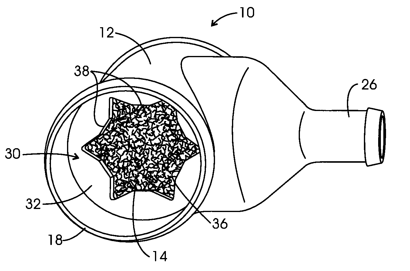
[0015]The outlet port end of the housing includes a downstream support device which facilitates the assembly of the filter, and defines the axial location of the filter in the housing. The support device is located downstream of the sump, preferably between the sump and the outlet port of the housing. In one embodiment, the support device could be disc-shaped and could have a circular peripheral configuration, which fits closely within the inner diameter of the housing, and is fixed to the housing such as with adhesive, friction fit, or by other appropriate means. The support device includes in one embodiment a central aperture, which could have a “star-shaped” configuration, that is, with inwardly-projecting portions which facilitate locating and supporting the downstream end of the media.
[0018]The collected oil then passes downwardly by gravity through the drain port in the sump, where it can be returned to the engine. The substantially oil and emission-particulate-free gases then continue to pass through the media, through the aperture(s) in the support device, and out through the outlet port in the housing, where the gasses can then be directed to a turbocharger, to atmosphere, to or other appropriate location. In a closed crankcase application, this will prevent oil and contaminants from entering the turbocharger which would cause damage and premature wear to the turbo components. In an open crankcase application, the device will reduce the amount of oil and contaminants which would be exposed to the atmosphere. The result is a cleaner burning and more efficient engine that will benefit the environment.

Problems solved by technology

Crankcase emissions result from gas escaping past the piston rings of an internal combustion engine and entering the crankcase due to high pressure in the cylinders during compression and combustion.
As the blow-by gas passes through the crankcase and out the breather, the breather becomes contaminated with oil mist.
In closed systems, the crankcase emissions are directed into the engine intake system causing internal engine contamination and loss of efficiency.
The oily crankcase emissions coat engine sites, such as the inside of engine compartments or chambers, fouling expensive components and increasing costs, such as clean-up, maintenance and repair costs.
The accumulation of contaminants on these components reduces efficiency, performance and reliability of the engine.

Method used


Image

  • Crankcase ventilation filter/pre-separator
  • Crankcase ventilation filter/pre-separator
  • Crankcase ventilation filter/pre-separator

Examples


Embodiment Construction

[0003]Emission controls for internal combustion engines have become increasingly important as concerns over the environment have risen. One area where improvement has been noted is in crankcase emission controls.

[0004]Crankcase emissions result from gas escaping past the piston rings of an internal combustion engine and entering the crankcase due to high pressure in the cylinders during compression and combustion. As the blow-by gas passes through the crankcase and out the breather, the breather becomes contaminated with oil mist. The gas also contains wear particles and air / fuel emissions. In closed systems, the crankcase emissions are directed into the engine intake system causing internal engine contamination and loss of efficiency.

[0005]The oily crankcase emissions coat engine sites, such as the inside of engine compartments or chambers, fouling expensive components and increasing costs, such as clean-up, maintenance and repair costs. As the oily residue builds up on critical en...


PUM

PropertyMeasurementUnit
Diameteraaaaaaaaaa

Abstract

A filter for removing liquid contaminants from a fluid stream. The filter includes a housing with an internal chamber and inlet and outlet ports. A sump with a drain port is located intermediate the inlet and outlet ports. Expanded aluminum filter media in bunched form is located in the chamber and can be inserted through the inlet port. A support disc supports the downstream end of the filter media at a predetermined axial location within the chamber, and has an aperture allowing contaminant-free gas flow downstream to the outlet port. The liquid contaminants and emission particles are separate by the filter media and agglomerate for collection in the sump and for draining through the drain port, while the support disc prevents the liquid contaminants from migrating downstream along the walls of the housing.

Description

CROSS-REFERENCE TO RELATED CASES[0001]The present application claims the benefit of the filing date of U.S. Patent Application Ser. No. 61 / 013,451, filed Dec. 13, 2007, the disclosure of which is fully incorporated herein by reference.FIELD OF THE INVENTION[0002]The present invention is directed toward a crankcase ventilation filter for diesel or gas engines.DETAILED DESCRIPTION OF THE INVENTION[0003]Emission controls for internal combustion engines have become increasingly important as concerns over the environment have risen. One area where improvement has been noted is in crankcase emission controls.[0004]Crankcase emissions result from gas escaping past the piston rings of an internal combustion engine and entering the crankcase due to high pressure in the cylinders during compression and combustion. As the blow-by gas passes through the crankcase and out the breather, the breather becomes contaminated with oil mist. The gas also contains wear particles and air / fuel emissions. I...

Claims


Application Information

Patent Timeline
IPC IPC(8): F02M35/024
CPCB01D46/0031F01M2013/0438F01M13/04B01D2279/35
Inventor FRAZIER, JR., RONALD G.TICE, DAVID
Owner PARKER HANNIFIN CORP
Learn More