
Apparatus for Reducing Nitrogen Oxide in Exhaust Pipe

a technology of nitrogen oxide and exhaust pipe, which is applied in the direction of mechanical apparatus, machines/engines, separation processes, etc., can solve the problems of offensive order and reduced nitrogen oxide purification efficiency, and achieve the effect of enhancing the purification efficiency of nitrogen oxide in the exhaust gas

Active Publication Date: 2009-06-18
HYUNDAI MOTOR CO LTD +1
View PDF31 Cites 6 Cited by
  • Summary
  • Abstract
  • Description
  • Claims
  • Application Information

AI Technical Summary

Benefits of technology

The present invention provides an apparatus for reducing nitrogen oxide in an exhaust pipe. The apparatus includes a nitrogen oxide sensor, a nozzle, a mixer, and a de-nitrification catalyst reaction device. The nozzle injects urea based on the amount of nitrogen oxide measured by the sensor. The mixer mixes the urea with the exhaust gas, and the de-nitrification catalyst reaction device purifies the nitrogen oxide. The apparatus is designed to improve the mixing rate of urea and exhaust gas, and enhance the purification efficiency of nitrogen oxide in the exhaust gas. The exhaust pipe, mixer, inlet portion of the de-nitrification catalyst reaction device, and de-nitrification catalyst reaction device may be coaxially disposed. The invention also includes a stabilizing portion between the mixer and the inlet portion of the de-nitrification catalyst reaction device. The invention has advantages of improving the efficiency of nitrogen oxide reduction in exhaust gas.

Problems solved by technology

However, the exhaust apparatus of the vehicle is set at a predetermined length, so the urea and the exhaust gas cannot be uniformly mixed to flow into the urea-SCR such that the purification efficiency of the nitrogen oxide is reduced.
Also, the ammonia that remains by not reacting with the nitrogen oxide is discharged to the outside and causes an offensive order from the exhaust gas.

Method used


Image

  • Apparatus for Reducing Nitrogen Oxide in Exhaust Pipe
  • Apparatus for Reducing Nitrogen Oxide in Exhaust Pipe
  • Apparatus for Reducing Nitrogen Oxide in Exhaust Pipe

Examples


Embodiment Construction

[0030]Reference will now be made in detail to various embodiments of the present invention(s), examples of which are illustrated in the accompanying drawings and described below. While the invention(s) will be described in conjunction with exemplary embodiments, it will be understood that present description is not intended to limit the invention(s) to those exemplary embodiments. On the contrary, the invention(s) is / are intended to cover not only the exemplary embodiments, but also various alternatives, modifications, equivalents and other embodiments, which may be included within the spirit and scope of the invention as defined by the appended claims.

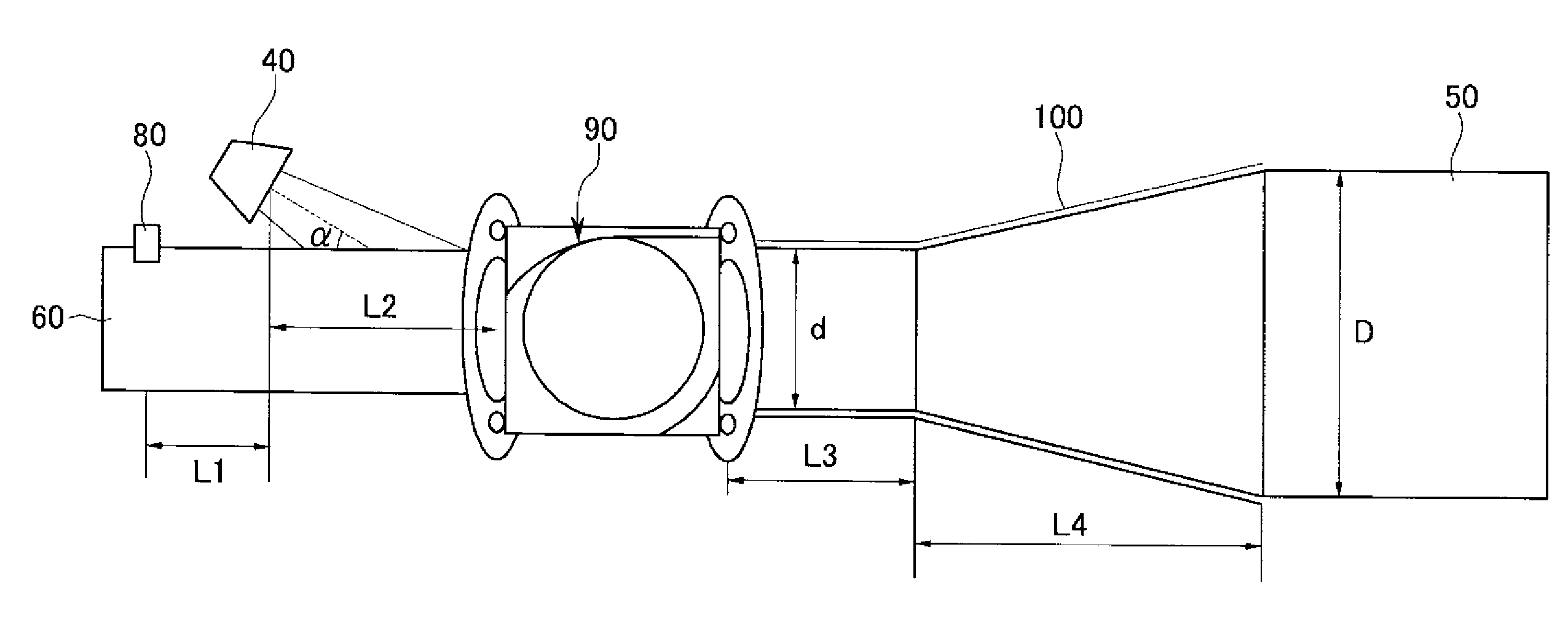
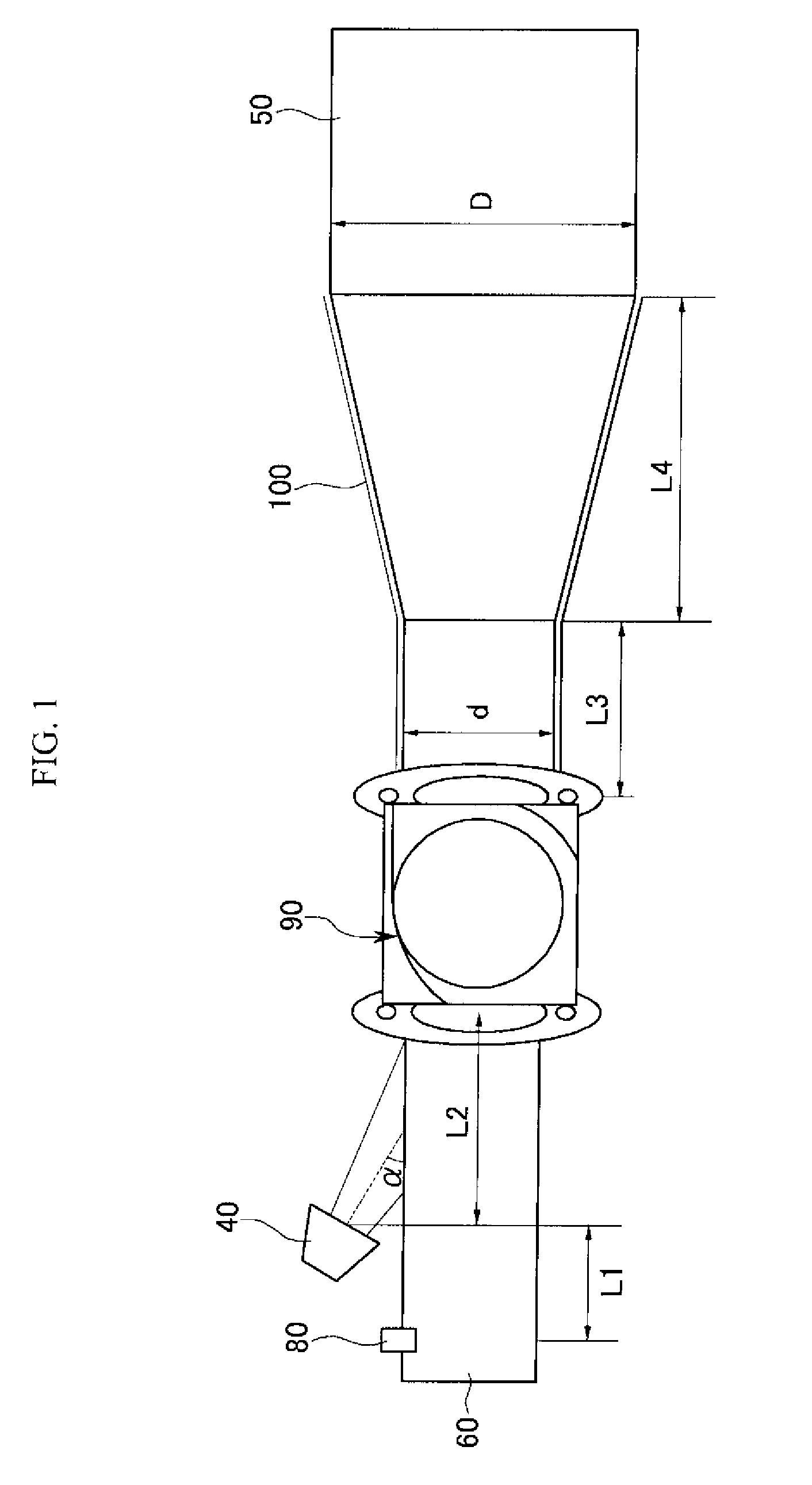
[0031]FIG. 1 is a schematic diagram showing an exhaust device in which a device for reducing nitrogen oxide in exhaust gas is applied according to various embodiments of the present invention.

[0032]As shown in FIG. 1, the exhaust gas of an engine 10 flows in an exhaust pipe 60, in which a plurality of harmful ingredients are eliminate...


PUM

PropertyMeasurementUnit
injection angleaaaaaaaaaa
lengthaaaaaaaaaa

Abstract

An apparatus for reducing nitrogen oxide in an exhaust pipe, may include a nitrogen oxide sensor that is mounted in the exhaust pipe and that measures amount of the nitrogen oxide in exhaust gas, a nozzle that is disposed on the exhaust pipe to be spaced apart from the nitrogen oxide sensor to a downstream side of the nitrogen oxide sensor by a first predetermined length and that injects urea corresponding to the amount of the nitrogen oxide, a mixer that mixes the urea with the exhaust gas and that is disposed at a downstream side of the nozzle on the exhaust pipe to be spaced apart by a second predetermined length from the nozzle, and a de-nitrification catalyst reaction device that is disposed at a downstream side of the mixer on the exhaust pipe, purifies the nitrogen oxide, and includes an inlet portion having a predetermined length.

Description

CROSS-REFERENCE TO RELATED APPLICATION[0001]The present application claims priority to Korean Patent Application Number 10-2007-0131561 filed Dec. 14, 2007, the entire contents of which Application is incorporated herein for all purposes by this reference.BACKGROUND OF THE INVENTION[0002]1. Field of the Invention[0003]The present invention relates to an apparatus for reducing nitrogen oxide of exhaust gas, and more particularly to an apparatus for reducing nitrogen oxide for mixing urea with the nitrogen oxide so that the purification rate of the nitrogen oxide in the exhaust gas can be improved.[0004]2. Description of Related Art[0005]Generally, exhaust gas that is exhausted through the exhaust manifold of an engine is induced to pass through a catalytic converter that is mounted in the middle of an exhaust pipe to be purified, and the noise thereof is reduced while passing through a muffler and the exhaust gas is discharged to the outside through a tail pipe. The catalytic convert...

Claims


Application Information

Patent Timeline
Patent Type & Authority Applications(United States)
IPC IPC(8): F01N3/18
CPCB01D53/9431B01D2251/2067B01D2257/404F01N3/208Y02T10/24F01N2240/20F01N2470/20F01N2560/026F01N2610/02F01N13/08Y02T10/12Y02A50/20F01N3/20F01N3/28
Inventor KIM, CHANG DAE
Owner HYUNDAI MOTOR CO LTD
Learn More